Will CFAF240400D-030T work for status indicator screen?

NATS

New member
Hello All,

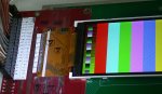
I’m looking at the crystalfontz CFAF240400D-030T RGB display.

https://www.crystalfontz.com/product/cfaf240400d030t-display-module-tft-lcd-240x400-graphical

The reason I’m looking at it is because of size. It is a near perfect fit for my needs. Through research I’m learning this display may not be the easiest to interface with but size is exactly what we need.

My Application:

I’m designing a prototype status indicator screen for an airplane cockpit. Input’s from multiple sources will be coming into a master control unit (MCU). In this case we are prototyping the MCU as a raspberrypi 3 Model B.

The concept is to have a PI run a script that loops through the GPIO pins listening for state changes. If a pin changes states, the LCD is to display text (colored text and background color) that indicates the current condition. Example; engine fire, low fuel, cabin pressure, door unlocked, door open and so forth. The background color behind each text string will be unique. Depending on the severity of the condition the background may be red and text yellow to indicate emergency which requires immediate attention.

This will be the first time I’m working with a TFT LCD. I’m also very green with raspberrypi’s. I’m a mechanical engineer stretching my legs with electrical engineering concepts.

Couple questions that I could use some confirmation or high level direction on.

1. Are there any known tutorials on connecting this display to a PI?
2. Are there any known recommendations for connecting components that we should consider? (example IDA connector and ribbon cable to GPIO pi header)
3. Is this LCD capable of I2C or SPI communication? Or just parallel interface?
4. Are there any known wiring diagrams or tutorials to help with setup?
5. Is there any known recommended chip, breakout board or custom cable that could consolidate the amount of wires required to drive data to and from the LCD and PI? (example serial to parallel converter)

Any high level guidance or product selection is appreciated. Thank you!
Looking for additional LCD resources? Check out our LCD blog for the latest developments in LCD technology.
 
3. Is this LCD capable of I2C or SPI communication? Or just parallel interface?
Parallel only.
5. Is there any known recommended chip, breakout board or custom cable that could consolidate the amount of wires required to drive data to and from the LCD and PI? (example serial to parallel converter)
You can get the display mounted on a carrier/breakout board.
https://www.crystalfontz.com/product/cfaf240400d030tcb-display-lcd-240x400-tft-breakout

I did a test project using this display (an earlier version) several years ago, interfaced to an ATMEGA dev board. I have a "c" source file available that draws a test pattern on the screen. I also offer a "c" bundle to put text on graphic displays that is available in another section of this site. So I could maybe provide some help with the physical I/F, and coding, but I don't know what language you are using on the R-PI.

As for airplane cockpit, how will you handle the wide dynamic range of lighting conditions? Will the display wash-out in sunlight? How to handle backlight dimming for night use? Etc.
 

Attachments

NATS

New member
Appreciate the reply.

I am aware of the carrier board option with the LCD. I think that will help our design out. As for the C code I think we will go that route once we move towards a fully embedded design. I’ve been directed to use a raspberry pi with Python for initial prototype.

My Idea is to use a I/O expander chip like the MCP23017 found here
https://www.adafruit.com/product/732 with the raspberrypi.

My understanding is that it expands the number of pins using the I2C protocol.

What I’m not sure about and I’m not seeing any supporting information or other DIY projects is running a parallel interface LCD with this I/O expander chip controlled by a PI.

Can this strategy work?
 

CF Tech

Administrator
You need to be aware of bandwidth and the related update speed.

Assuming 400KHz I[SUP]2[/SUP]C and a 240x400 16-bit display driven throgh the MCP23017 or similar:

(240x400 pixel) * (16 bits/pixel) / (400000 bits/second) = 3.84 seconds

This lower-bound calculation assumes no overhead (address bytes, start & stop bits) -- so real life will be worse--perhaps significantly.

The best performance would be to use the rPI's native parallel TFT interface, but this will use most of the rPI's GPIO pins.

Can you get SPI on the rPI? Looks like yes.

Using SPI mode at 7.8MHz on this similarly sized display:
https://www.crystalfontz.com/product/cfaf240320v020t-240x320-color-TFT


(240x320 pixel) * (16 bits/pixel) / (7800000 bits/second) = 0.16 seconds

Again, this is a lower-bounds, actual times will be slower.

Can you go smaller? This smaller/cheaper display would update nicely over SPI:
https://www.crystalfontz.com/product/cfaf128128b0145t-graphic-tft-128x128


(128x128 pixel) * (16 bits/pixel) / (7800000 bits/second) = 0.033 seconds

Will you make just one of these, or are you looking at a production run?
 

NATS

New member
Okay Thank you for the information.

What I read is that it could work but there would be considerable delay in updates to the LCD. Is that correct? Best case at 3.84 seconds per the math for information to be displayed.

I think in most application this lag could be a big issue. However, it might not be much of an issue for us because we would be using it as a status indicator. Where refresh rate is not a concern and no graphical image structures are to be displayed. Simply a background color with text displayed over the background color.

So, again to confirm, using a MCP23017 or similar chip could work but there will be considerable delay with updates to the LCD?

Right now we are working on a prototype concept for our investors. If they like the concept we could see a production run.

Thank you for the information.
 

CF Tech

Administrator
. . . considerable delay in updates to the LCD. Is that correct? Best case at 3.84 seconds per the math for information to be displayed. . . .
Using I[SUP]2[/SUP]C and the converter chip, the update will wipe down the screen, taking ~4 to ~6 (or more) seconds. It will not delay then change all at once.

. . . using a MCP23017 or similar chip could work . . .
Yes, it could work, but it would be way simpler to use a native SPI or native I[SUP]2[/SUP]C display.

Simply a background color with text displayed over the background color.
If that is all you are after, why use a TFT? Here are some nice-looking SPI OLEDs that would be an order of magnitude less complex to implement:
https://www.crystalfontz.com/product/cfal1602c-16x2-character-oled?bundle=4249


Here is a native I[SUP]2[/SUP]C graphic OLED, which would be simple to connect, and can display icons / simple graphics:
https://www.crystalfontz.com/product/cfal12864ky-128x64-small-oled-display


https://www.crystalfontz.com/product/cfal12864g024w-128x64-2-4inch-white-oled-module


Keep in mind that your project that you want to show to the investors is not a display. The display is just something you need to get done as simply and quickly as possible so you can move on to the real problem you are trying to solve.

Using a parallel, full-color TFT over an I[SUP]2[/SUP]C expander to display textual information is a huge technical problem & overkill compared to the 3 wires (plus power and ground) of a SPI OLED.
 
... no graphical image structures are to be displayed. Simply a background color with text displayed over the background color.
Just want to clarify that on graphic displays, text IS a graphic image, typically a bitmap type of structure. So as CF Tech says, the higher the screen res, the slower the update will be, especially if ser-parallel conversion is used.
 

NATS

New member
Thanks for the information and recommendations.

I have a good understanding about the options and BKM's

I'll take this to our team and see how we should proceed.

Cheers!
 

NATS

New member
Project is moving forward via DPI mode on the Raspberry-pi 3 B+, using the BCM pin configuration.

Got a new question wiring in a RGB 666 configuration.

When configuring via the 18-bit mode, how do the RGB's wires correlate with the DB-17 to DB-0 pins?

I'll be using all the pins but I have not yet wrap my head around which pin goes where. Is it in order RGB to DB-17 to DB-0? 6 pins each. Where GPIO 25 (Red 7) = DB-17 & GPIO 4 (Blue 2) = DB-0? This is my assumption. I understand the Pi map just not 100% confident on the wiring.

To help pull this together I've created a KiCAD schematic and will start connecting pins soon. Would love to share the results when complete.

Thank you!
 

NATS

New member
It does, thank you!

It looks like my assumption was correct. Thanks for pointing me to the controller datasheet.
 
Top