RaduMolasar
New member
Dear gentlemen,
Newbie here...
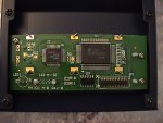
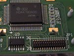
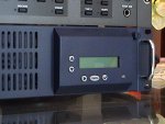
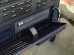
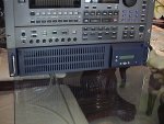
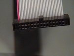
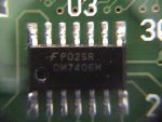
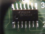
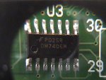
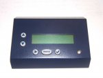
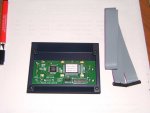
I just purchased a rackmount server case with included LCD module, but the manufacturer knows nothing of how to connect it.
I've searched all over the net with no luck.
Can anybody shed some light on it? Help!!
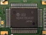
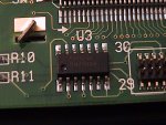
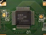
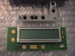
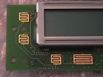
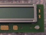
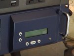
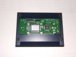
The LCD module is installed on (screwed onto) the front cover (panel) door of the server case.
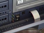
At first I thought it connected to an internal alarm/fan board, but the included alarm/fan board has no such connector... in fact, not connector at all except for fans and temp sensors...
Thanks!
Mike
Newbie here...
I just purchased a rackmount server case with included LCD module, but the manufacturer knows nothing of how to connect it.
I've searched all over the net with no luck.
Can anybody shed some light on it? Help!!
The LCD module is installed on (screwed onto) the front cover (panel) door of the server case.
At first I thought it connected to an internal alarm/fan board, but the included alarm/fan board has no such connector... in fact, not connector at all except for fans and temp sensors...
Thanks!
Mike
Looking for additional LCD resources? Check out our LCD blog for the latest developments in LCD technology.
Attachments
-
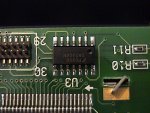
 DSCF1214x.JPG152.1 KB · Views: 948
 -
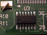
 DSCF1215x.JPG170.2 KB · Views: 836
 -
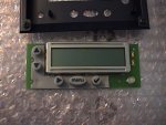
 DSCF1216x.JPG143.6 KB · Views: 824