how to connect CFAG160160B

kayimguney

New member
hello..
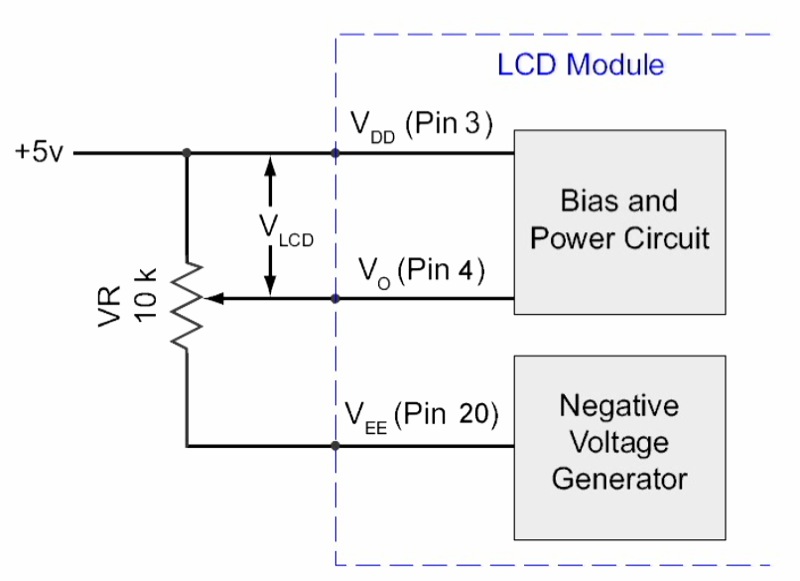
i tried to connect my module to power but i couldn't.. i have uploaded my connection circuit.. i think that connection is true but i couldn't figure what's wrong.. i tried both with 10K and 20K pots.. sometimes i see some chineese characters on screen but they are coming on and off continuously i couldn't see stabilized screen.. and when i cut off vdd and connect it again i couldn't see the previous screen..
waiting for help..
thank you..

Looking for additional LCD resources? Check out our LCD blog for the latest developments in LCD technology.
 

Attachments

kayimguney

New member
without initialization what should i see on the screen?
i know i didn't do initialization but i can't set the contrast.. i want to set contrast and be sure that there is no problem with power connections then do initialization and other things..
when i try to set contrast i saw several different screens.. in one screen dots are placed in the screen so slowly that i can see dots are placed and it had a look like shifting screen..
i hope i told my problem clearly.. i mean i think i have a problem with connections..
waiting for help..
thank you..
 
Before the display is initialized, the screen content is unpredictable, most likely garbage like you are seeing. Also, setting the contrast before doing initialization is not a good method, because when the init is performed, the mode and duty cycle are set, which will affect the contrast. Without having duty cycle set, the contrast is unpredictable.
 

CF Tech

Administrator
You cannot get the contrast "perfect" before initialization, but if you set Vlcd according to the data sheet, then it will be close enough that when you get the display initialized and send some data to it, you will be able to see it.

For the CFAG160160B, adjust Vo (pin 4) to -12.3v (for Vdd = 5v, this is Vlcd = 17.3v)

That will get the contrast close enough for starters.
 

kayimguney

New member
when the init is performed, the mode and duty cycle are set, which will affect the contrast. Without having duty cycle set, the contrast is unpredictable.
in the screen not all dots are placed at the same time.. i can see like %15 of the dots vertically placed and shifting down.. is this because i didn't set duty cycle?
if don't do initialization, does duty cycle is randomly decided? i said i see %15 of the dots but when i cut power and connect it again that %15 changes everytime.. sometimes it is %30 or something like that..

and i don't think this is close enough.. i think there is something else that i am doing wrong..

and is there any easier way to initialize? in wintest the codes are too long, is it just for initializing? i just wanna see LCD is working properly without sending data and if necessary initializing it.. is that impossible?

thank you for help..
 
i just wanna see LCD is working properly without sending data and if necessary initializing it.. is that impossible?
Yes, that is impossible. The display is functioning randomly until it is initialized.

You MUST initialize by sending the setup commands according to how you want to use the display. The WinTest code does more than just initialize the display; it shows test patterns also.
 

kayimguney

New member
thank you so much for help.. i wish i has asked this before.. i spend lots of time to see something on screen without initializing..
i don't understand the code in wintest.. i know that it is not just for initialization but i dont get which parts should i use.. if you help me with that too it will be great..
thank you..
 

kayimguney

New member
hello again..
i basicly understand what wintest code does.. but i need to know how some functions work..
the functions are defined like this:

#define SET_E (DlPortWritePortUchar(CONT_ADDR,(control&=~0x01)));(Delay())

but i cant see what DlPortWritePortUchar function does.. i think it is in the .dll file.. but icant open it..
is there any way to know what does DlPortWritePortUchar function does?

i know those functions are setting the registers but i couldn't manage to do it..
thank u for help..
 

kayimguney

New member
im just using this part of the code..
isn't this part had to make display on?
or am i doing something wrong?

Code:
void COM_W(ubyte data)
  {
  DATA(data);
  SET_RS;
  CLR_CS;
  //R/W is hardwired low
  Sleep(10);
  SET_E;
  Sleep(10);
  CLR_E;
  Sleep(10);
  SET_CS;
  }
void DATA_W(ubyte data)
  {
  DATA(data);
  CLR_RS;
  CLR_CS;
  //R/W is hardwired low
  Sleep(10);
  SET_E;
  Sleep(10);
  CLR_E;
  Sleep(10);
  SET_CS;
  }

void CP_COMMAND(ubyte comm_reg, ubyte data_reg)
  {
  COM_W(comm_reg);
  DATA_W(data_reg);
  }

void CCFAG_WinTestDlg::OnInitialize() 
  {
	CWaitCursor wait;

  //0 => 0x378, 1 => 0x278. 2 => 0x3BC
  switch(m_address.GetCurSel())
    {
    case 1:
      port_data_address=0x278;
      break;
    case 2:
      port_data_address=0x3BC;
      break;
    default:
      port_data_address=0x378;
      break;
    }
  port_control_address=port_data_address+2;

  ubyte
    i;
  i=0;

  //Idle the control lines & reset the display
  CLR_RES;
  CLR_E;
  CLR_RS;
  SET_CS;
  DATA(0);
  Sleep(10);
  SET_RES;
  Sleep(10);

  //MOV     COMM_REG,#00H           ;Command code--Mode control
  //MOV     DATA_REG,#32H           ;Set 00110010
  //LCALL   CP_COMMAND              ;Command complete
  CP_COMMAND(0x00,0x32);
}
i didnt use this part.. i dont understand why i had to use..
Code:
CWaitCursor wait;

  //0 => 0x378, 1 => 0x278. 2 => 0x3BC
  switch(m_address.GetCurSel())
    {
    case 1:
      port_data_address=0x278;
      break;
    case 2:
      port_data_address=0x3BC;
      break;
    default:
      port_data_address=0x378;
      break;
    }
  port_control_address=port_data_address+2;
 
First, you need to explain what you using to control the display. Are you connected to a PC parallel port, or a separate microcontroller? What language will you use to write your code?

The code from WinTest is intended to communicate to a display through a PC parallel port, using a dll to do the actual I/O. The sections that you posted are the command and data write routines. You have not included all of the init commands.

Here is a section of my code, showing the init values:
Code:
/***************************************
    lcd display constants
***************************************/
#define GR_MODE     0        // mode register
#define GR_PITCH    1        // character H & V pitch register
#define GR_HORIZ    2        // horiz chars or bytes register
#define GR_DUTY     3        // duty cycle register
#define GR_CURP     4        // cursor posn register
#define GR_STRTL    8        // display start addr L register
#define GR_STRTH    9        // display start addr H register
#define GR_CURAL    0xA        // cursor addr L register
#define GR_CURAH    0xB        // cursor addr H register
#define GR_WRITE    0xC        // write instruction
#define GR_READ     0xD        // read instruction
#define GR_BCLR     0xE        // bit clear instruction
#define GR_BSET     0xF        // bit set instruction

#define GR_INILEN    10        // number of items in init table

static const BYTE LCDIni[GR_INILEN][2] = {
        GR_MODE, 0x10,
        GR_PITCH, 0x77,
        GR_HORIZ, 19,
        GR_DUTY, 159,
        GR_CURP, 0,
        GR_STRTL, 0,
        GR_STRTH, 0,
        GR_CURAL, 0,
        GR_CURAH, 0,
        GR_MODE, 0x32    // graphic mode normally
};
That code can be found in a link at the bottom of this thread https://forum.crystalfontz.com/showthread.php?t=4465
 

kayimguney

New member
no im not using PC parallel port.. i know that the code is for pararllel port but i didnt use exactly that code..
im using fpga..
i just want to set display ON..

CP_COMMAND(0x00,0x32);

this part of code is for that i think..

i wrote this but it didnt work..

0x00 for mode reg
0x32 for display ON and Graphic mode..

after i did this i expect the back light to turned on but it didn't..
what should i do?
i dont think i should set other registers for that..
 
You cannot just issue only a MODE command and expect the display to work. You need to issue commands to all the registers from 0x00 to 0x0B. Take a look at my code above, at the init list. That is what you need to do to initialize the registers.
0x00 for mode reg
0x32 for display ON and Graphic mode..

after i did this i expect the back light to turned on but it didn't..
The back light is not controlled by any command, it is only turned on by the voltage applied to the backlight terminals (through a current limiting resistor).
 

kayimguney

New member
but there is a line in datasheet and it writes display ON/OFF i want it to be on and write my code for that..
what does that display on/off means then? i thought it is backlight.. i was wrong i guess and now i got what does it do..
thank u for your help i really appriciate it..
i ll try something more..
 
The Display ON/OFF bit in the mode register will enable or disable the data in the display memory to show on the screen. This will only work when the display has been initialized properly, and there is data in the memory to be displayed.

When you first apply power and do the initializing of the registers, then if the display ON/OFF bit is set to ON, the display could show whatever random data is in the memory (if the mode and duty registers are set properly).

As part of the init routine you will need to clear the memory by writing all 0's in graphic mode or all blanks (0x20) in text mode. Otherwise you will see random pixels or characters, as you have already experienced. Notice in my code that the first mode command is set to display OFF, and then the other registers are set, and at the end the mode is set to display ON. You may want to keep the display OFF until after you clear the memory, so the garbage does not show.
 

kayimguney

New member
i just wanna ask few more things..

now i just want to turn display off and then turn display on..
i had a button for ON and button for OFF..
i just wanna do this so i just set mode control register right? i mean i dont care what character pitch is so i wont set Character pitch Reg or i wont set Time division Reg...
that wouldnt be problem i hope..
im just willing to be able to send some data.. if i can do that i can easily set other registers..

and im using
rs: 1 for active - 0 for inactive
cs: 0 for active - 1 for inactive
en: 1 for active - 0 for inactive
reset: 0 for active - 1 for inactive

are these wrong? i took this from datasheet but i could have taken wrong..

and last question.. for setting display off and on im doing these commands..


to set off

set data=0x00
set rs
clear cs
delay 10 ms
set en
delay 10 ms
clear en
delay 10 ms
set cs

to set on

set data=0x32
clear rs
clear cs
delay 10 ms
set en
delay 10 ms
clear en
delay 10 ms
set cs

is this wrong??

set=active
clear=inactive

thank you so much for help..,

btw u didnt use cs pin but i have cs pin..
 
Last edited:
i just wanna do this so i just set mode control register right? i mean i dont care what character pitch is so i wont set Character pitch Reg or i wont set Time division Reg... that wouldnt be problem i hope..
That IS a problem. You MUST set the time division (duty cycle) and pitch registers or the display will not funtion correctly. I do not understand why you are not willing to set the registers for initialization, you can not expect the display to work otherwise.
and im using
rs: 1 for active - 0 for inactive
cs: 0 for active - 1 for inactive
en: 1 for active - 0 for inactive
reset: 0 for active - 1 for inactive

are these wrong?
RS is not "active" or "inactive", it is an address bit to select instruction (RS=1) or data (RS=0). The other signals are correct.
and last question.. for setting display off and on im doing these commands..

to set off

set data=0x00
set rs
clear cs
delay 10 ms
set en
delay 10 ms
clear en
delay 10 ms
set cs

to set on

set data=0x32
clear rs
clear cs
delay 10 ms
set en
delay 10 ms
clear en
delay 10 ms
set cs

is this wrong??
You are missing a lot of code. Each one of your "set off" and "set on" is only sending one byte. For a command, you must send two bytes: first the instruction (register number), then the data for the register. So for display off in graphic mode, send 0x00 (RS=1), then 0x12 (RS=0). For display on in graphic mode, send 0x00 (RS=1), then 0x32 (RS=0).
Code:
to set off

set data=0x00
set rs
clear cs
delay 1 ms
set en
delay 1 ms
clear en
delay 1 ms
set data=0x12
 clear rs
 delay 1 ms
 set en
 delay 1 ms
 clear en
 delay 1 ms
 set cs

to set on

set data=0x00
 set rs
 clear cs
 delay 1 ms
 set en
 delay 1 ms
 clear en
 delay 1 ms
 set data=0x32
  clear rs
  delay 1 ms
  set en
  delay 1 ms
  clear en
  delay 1 ms
  set cs
 

kayimguney

New member
this is what i have done.. tried to do what have u done in your code..

cs=always 0
reset=always 1

to turn display off
Code:
set rs to instruction
set data to 0x00
delay
set en to 1
delay 
set en to 0
delay

set rs to data
set data to 0x12
delay 
set en to 1
delay 
set en to 0
delay
to set char pitch
Code:
set rs to instruction
set data to 0x01
delay
set en to 1
delay 
set en to 0
delay

set rs to data
set data to 0x77
delay 
set en to 1
delay 
set en to 0
delay
to set no of char
Code:
set rs to instruction
set data to 0x02
delay
set en to 1
delay 
set en to 0
delay

set rs to data
set data to 0x19
delay 
set en to 1
delay 
set en to 0
delay
to set duty
Code:
set rs to instruction
set data to 0x03
delay
set en to 1
delay 
set en to 0
delay

set rs to data
set data to 0x9F
delay 
set en to 1
delay 
set en to 0
delay
to turn display on
Code:
set rs to instruction
set data to 0x00
delay
set en to 1
delay 
set en to 0
delay

set rs to data
set data to 0x32
delay 
set en to 1
delay 
set en to 0
delay
this doesn't work and i couldn't manage to solve the problem..
i tried several more things which are different than this but none of them has worked..
i'm running out of time and i got almost nothing :s

i don't know if u can help more.. u helped a lot and i should have make this thing worked by now but i couldn't.. if u can tell me something else some more information it will be great.. thank you so much for help..
 
Your code sequence looks like it should work, except for one mistake. For the "H_CHAR" (0x2) register you have data = 0x19, that should be "19" (0x13). The next two things to check:

1. is your wiring correct?

2. is your timing within spec?

Do you have any way to look at your signals, like a logic probe or o'scope? At this point, you are not writing any data (pixels) to the display, so I can't predict what the screen will show. Maybe later, if I can find my CFAG160, I will try your incomplete init sequence, and see what happens.
 
Top