how to connect CFAG160160B

Poor signal quality could be caused by long unshielded wires (more than 12"/300mm perhaps), or poor quality grounding, or high resistance, or too much capacitance. Without seeing your hardware setup, I can not say whether you have any of these conditions. It may be possible that you have some data lines or control lines touching another slightly, so that the signals conflict and cause a voltage somewhere between the 1 and 0 voltage levels. This is what you need a scope to see, while the signals are actually changing.

BTW, because of another thread that mentions potential problems with the Vee/contrast circuit, I am wondering if you use the RESET input as part of your initialization procedure.
 

kayimguney

New member
Poor signal quality could be caused by long unshielded wires (more than 12"/300mm perhaps), or poor quality grounding, or high resistance, or too much capacitance. Without seeing your hardware setup, I can not say whether you have any of these conditions. It may be possible that you have some data lines or control lines touching another slightly, so that the signals conflict and cause a voltage somewhere between the 1 and 0 voltage levels. This is what you need a scope to see, while the signals are actually changing.
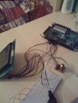
i attached my hardware.. my wires are not too long.. im pretty sure that none of them are touching each other.. i didn't use any capacitance or resistor between fpga and display..

BTW, because of another thread that mentions potential problems with the Vee/contrast circuit, I am wondering if you use the RESET input as part of your initialization procedure.
i didn't understand this.. my reset pin is H when im doing initialization..
 

Attachments

.. i didn't use any capacitance or resistor between fpga and display..
Capacitance always exists. Usually it is not significant. But if you had something like a long ribbon cable or long shielded cable, the capacitance could affect the signals, and also cause cross-talk. Your hardware does not appear to have that problem. Resistance always exists. Usually it is very low for soldered or crimped connections. Sometimes a proto-board can have a poor connection with higher resistance.
.. my reset pin is H when im doing initialization..
Yes, but the comment intends to ask whether you USE the reset input, meaning that you take the reset low for a few milliseconds and then keep it high afterwards, before you start your initialization. You have not mentioned ever using the reset pin.

If I had a project that was not working (and I do have them sometimes), the first thing I would do is use a scope to find out if the signals look correct, because you can't tell that with a voltmeter or ohmmeter. You seem very reluctant to take this advice, so I can only suppose you are not in a hurry to find out why it doesn't work :confused:.
 

kayimguney

New member
i have a scope to use.. it is not my it is at school that's why i can't use it all the time.. but when i go to school i'll use scope and check my signals.. thanks for your care..

btw reset pin is L for a moment then H..
 
Top