Help with sed1565 initialization code

juanwor

New member
Hi,
I´m turning on the display after initializing it. The parameters I´m sending are:
Code:
void init_display()
{
    output_low(DISPLAY_RESET); /* Put RESET pin in low */
    delay_us(10);/*to guarantee timing*/
    output_high(DISPLAY_RESET); /* Put RESET pin in high */
    delay_us(2);/*to guarantee timing*/
    output_low(CS1); /*enable chip*/
    delay_us(2);/*to guarantee timing*/

    /*Start sending init commands*/
    disp_reset();/*0xE2*/
    disp_bias_set(LCD_BIAS_1_9);/*0xA2*/
    /*disp_ADC_sel(ADC_SELECT_NORMAL);/*0xA0*//*currently not sent*/
    /*disp_COM_dir(COMMON_OUTPUT_NORMAL);/*0xC0*//*currently not sent*/
    disp_v5(0x24);/*0x24*/
    disp_power_ctrl(POWER_CONTROL_SET | VOLTAGE_REGULATOR | VOLTAGE_FOLLOWER | 

BOOSTER_CIRCUIT);/*0x28|0x02|0x01|0x04 = 0x2F*/
    disp_elec_vol(0x24);/*0x20*/
    disp_on();/*0xAF*/
}
And here are the commands(CMD set A0=0):
Code:
void disp_reset()
{
    Write_Display(CMD,RESET_DISPLAY);/*0xE2*/
}

void disp_bias_set(UINT8 bias)
{
    Write_Display(CMD,bias);
}


void disp_v5(UINT8 ratio)
{
    Write_Display(CMD,ratio);
}

void disp_power_ctrl(UINT8 pwr)
{
    Write_Display(CMD,pwr);
}

void disp_elec_vol(UINT8 ratio)
{
	if (ratio<=0)
	    ratio = 0;

	if (ratio>=63)
	    ratio = 63;

    Write_Display(CMD,ELECTRONIC_VOLUME_SET);/*0x81*/
    Write_Display(CMD,ratio);
}

void disp_on()
{
    Write_Display(CMD, DISPLAY_ON);/*0xAF*/
}
My questions:
1- After the command disp_power_ctrl() I can measure -9.5 V as the reference voltage, that is right?

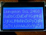
2- After this initialization I send data to the display BUT I see nothing...any suggestion?

This is the command used to send data:
Code:
void disp_wr(UINT8 datax)
{
    Write_Display(DATA,datax);/*DATA sets A0=1*/
}
Thanks
Looking for additional LCD resources? Check out our LCD blog for the latest developments in LCD technology.
 
Hi juanwor,
I wonder which display you are using that has the SED1565, and what circuit you are using for the charge pump caps, and what your input pin connections are for Vout, IRS, etc. It may not be important, but without knowing, I can't help in that area. BTW, in my use of the Optrex F-51320, the Vout voltage is -9.5 volts (refered to GND) and V5 is -4.7 volts.

Your init looks approximately correct, except for the Evolume/power control sequence. The data sheet indicates that the Evolume should be set before the power control is activated. I use a stepped sequence for power, turning on the charge pump first, then the regulator, then the follower, with delays in between (this is recommended in the Samsung KS0713 datasheet, and I use the same code for both chips). Epson says the init sequence should be completed within 5 mS, but I find that it doesn't matter if it takes 50 mS.

For the regulator ratio, I find that 0x26 works best (0x27 is too dark, and 0x25 or less gives no contrast). Are you able to make the screen become dark at all?

Also, I found that I needed to do the Evolume set again after the power control settled, or else I got poor contrast that was content-dependent.

Why did you comment out the disp_ADC_sel() and disp_COM_dir()?

I wonder if you downloaded my lcd code from the thread that you first posted in. That init code works well, and if you get desperate, you can try using it ;) .

Then there is the possibility that you have not got the column address set correctly, and your data is going off-display.:(
 
Last edited:

juanwor

New member
SED1565 for f-51553...help!

Cosmicvoid,

Firstly I really appreciate your help, it is very useful. Thank you.
Here´s the info:
Display: F-51553 (Optrex, very similar to 51320).
Circuit: 3X charge pump, 4.7uF between CAP2+ and CAP2-, CAP1+ and CAP1-, and Vout connected to CAP3- and through a 4.7uF capacitor to GND.
IRS: 5v
CS1,A0,RD,WR,RESET: connected to MPU output lines.
D0..D7: to MPU with parallel setup
P/S: set to parallel
C86: set to 8080
VR: not connected
V1..V5: through 1uF capacitors to 5v
Of course: Vcc=5v and GND=0v


Answers:
1- Are you able to make the screen become dark at all?
No, in fact I never saw the display to show anything (but I´m sure the display is ok, I have 3 to try).

2- Why did you comment out the disp_ADC_sel() and disp_COM_dir()? Because I tried everything and forgot to get back the comments, nothing in particular.

3- Yes, I downloaded your code but I wonder if it would work at 20MHz as I´m doing.


My questions:
1- Yes, I have almost the same Vout and V5 volts as you mention, I believe the power control command was sent ok, isn´t it???

2- When you say "I use a stepped sequence for power, turning on the charge pump first, then the regulator, then the follower, with delays in between": How do you split the power sequence? Do you split the OR´ed argument and send once at a time?

3- Other suggestions? Thanks again.
 
Ok, connections very similar to what I have, except I'm using 6800 mode.

#1 - Since you have -9.5 volts at Vout, I have to believe that the whole power init command sequence is working, and also that there is no wiring error.

#2 - Split like this:
Code:
disp_elec_vol(0x24);
delay_us(5000);
disp_power_ctrl(POWER_CONTROL_SET | BOOSTER_CIRCUIT); /*0x2C*/
delay_us(5000);
disp_power_ctrl(POWER_CONTROL_SET | BOOSTER_CIRCUIT | VOLTAGE_REGULATOR); /*0x2E*/
delay_us(5000);
disp_power_ctrl(POWER_CONTROL_SET | BOOSTER_CIRCUIT | VOLTAGE_REGULATOR | 
VOLTAGE_FOLLOWER); /*0x2F*/
delay_us(10000);
disp_elec_vol(0x24);
When I was experimenting with this display several years ago, I found that the delays made for more consistant contrast results. I don't know if other people have found them unnecessary or not. I decided it couldn't hurt.

#3 - Since you can use the NOP_CCS statement, you should have no trouble running at 20 MHz. You only need NOP_CCS to stretch out the write (or read) strobes to the 30 nS or 70 nS minimum width. You may not even need that, if the port output changes have an instruction between them. These displays have really fast interfaces. I don't even use the busy-flag check in my assembler version, I don't think you would need it either. So your write function would just be:
Code:
void Write_Display(UINT8 command, UINT8 datax)
{
    /* Load the control signals and data for a particular command. */
    if(command == CMD)
        output_low(DISPLAY_A0);
    else
        output_high(DISPLAY_A0);
    /* Place the data on the bus. */
    DATA_8 = datax;
    NOP_CCS;
    output_low(DISPLAY_WRITE);
    NOP_CCS;
    output_high(DISPLAY_WRITE);
}
There are still two items you didn't comment on, which could be important:
Did you try 0x26 for the resistor ratio command?
Did you do the Evolume command both before and after the power control commands?
You should experiment with both of those command values, and if you use 0x27 for the ratio, the screen should go dark, at least somewhat.
Perhaps you could try adding the "All points on" command, 0xA5, at the end of your init, to try to force all pixels on, just to see what happens.

I don't see any outputs to CS1. Are you sharing the data bus? If not, you could just tie it LOW, and save a I/O pin and possibly a timing issue.

I can't think of anything else to try at this point.
 
Last edited:

juanwor

New member
sed1565 all dark

cosmicvoid,

first thanks.
I was able to get an "all dark¨screen by combining V5=0x26 and EVol=0x2A (). That was the best situation but I could not do other thing.
At this point V5=-2,88 and Vout=-9,4.
I do not tried to modify V5 , I just get this screen modifing Evol while V5 was fixed. I should try the inverse situation...


Answer:
- CS1 is always low... however it occupies a pin.

Well, let me contact you in the near future if I have any other question... I think it´s a matter of commands parameters what´s happening, may be here we have different conditions and the voltage adjustments are different. I´ll let you know.

Thanks
 

juanwor

New member
Refresh needed for sed1565?

Hi,
I would like to know if it is needed some kind of refresh for sed1565 controller (F-51553 from optrex).
I can turn on the display and put all its points on but I cannot maintain this situation. What I see at this moment is that the -9.5 volts on Vout becomes 0,5v or other values.
I read about using a NOP but I´m not sure if it is needed.
I will appreciate help about this...thanks
 
I think maybe I should clarify about "dark" and "light" pixels on the screen. I believe the 51553 is like the 51320, in that it is transmissive, with a white LED backlight. So when all the pixels are off, the display is actually dark blue. When a pixel is on, it becomes clear, and the white shows thru.

So "all pixels on" means the display goes white, right? And your complaint refers to the contrast degrading in this situation, right?

As for the Vout voltage going toward 0 when all pixels are on ( or very many on), I saw the same effect in my early experiments. I conclude that the internal voltage boost/regulator/follower circuit is not capable of a "heavy load", and will sag badly when too many pixels are on. Since I don't ever try to turn more than about half the pixels on (my content = text and small graphics), then the contrast remains acceptable. So I have not done experiments to get it to work under heavy load (e.g. inverted data).

Perhaps increasing the value of the capacitors, especially C3, a lot may help, or at worst, using an external power source instead of the charge pump. It seems like the display should "just work OK" with the components you have, but since I have seen this effect also, I assume it is a shortcoming in the SED1565. I do not see any specification for the current output from the follower, nor for the dynamic requirement under heavy load.
I read about using a NOP but I´m not sure if it is needed.
I'm not sure what you mean (cpu NOP or display command NOP), I think it would have no effect.

If you experiment with cap values or external power, let me know what you discover. Here is a pic of 51320 test screen.
 

Attachments

juanwor

New member
Worked sed1565 !!

cosmicvoid,
thanks for you support! I could make the display work. The key was the bias setting. It was set as 1/9 and was needed 1/7. Now is working ok. I'm using 4.7uF as Vout capacitor and I works fine to display all points on.
 
Wow, very interesting. When I did my initial experiments with the Optrex display in late 2002, for some reason I found that 0xA2 (1/9) worked OK for the bias setting, and 0xA3 (1/7) gave some result that made me decide that 0xA2 was better. But I don't remember the details now. So I have been using 1/9 all this time.

Well, after reading your result, I just did a quick test using 1/7. It also works fine, but of course I had to change the V5 resistor ratio setting from 0x26 to 0x25 to bring the contrast back into the useful range.

It seems like maybe the 1/7 bias gives a little bit better contrast, but its hard to tell. But I wonder why I didn't get this result 2 years ago :( . So I will stay with the 0xA3 setting, which is the same as what I use on the CFAX displays. So thanks for the help, JuanWor !!! :D . Glad you got it working.

Edit: Well fooey, I just looked further into the data sheets, and both displays should use 1/7. For 1/7 in the SED1565, the code is 0xA3, but for 1/7 in the KS0713 the code is 0xA2. So my defines for bias were exactly backwards. This is the first I have seen that the two controllers have a difference in the command register values. Guess I need to pay more attention.
 
Last edited:

juanwor

New member
My results between 1/7 and 1/9 are very different. In fact with 1/9 I almost cannot see the points on. Another difference with what you have is that I have very little variation when change V5 resistor ratio from 0x25 to 0x27 (I´m using 0x27 during my experiments).
Well, may be we have any other hardware difference.
And of course, thanks again ...
 

himalaya

New member
Hi I am trying to use SED1565 EPSON lcd with mpc5645s but i am having difficulty initialising and printing anything on lcd. Could you help me with this? Thanks
 
Need more information.
What is the model # of the display?
Can you describe your circuit connections with the cpu?
What configuration are you using for the Vout (electronic volume) circuit?
What initialization commands are you sending?

Possible problems:
Interface to cpu is wrong, or timing of signals is wrong.
The LCD voltage (Vout) is not high enough, so you have no contrast.
Init data is setting bad register values.

I presume you understand the discussion in the earlier part of this thread.
 

himalaya

New member
What is the model # of the display?
--S1D15605
Can you describe your circuit connections with the cpu?
3* step-up voltage circuit .
LCD is powered up by 3.3 V from power supply.
I am sending these:
#define S1D15605_DISP_OFF 0xAE
#define S1D15605_DISP_ON 0xAF
#define S1D15605_DISP_START_LINESET 0x40
#define S1D15605_PAGE_ADDRESS 0xB0
#define S1D15605_COLUMN_ADDRESS 0x???
#define S1D15605_STATUS_READ 0x?? the busy flag... page 28.go over that??
#define S1D15605_DISPLAY_DATA_WRITE 0x??
#define S1D15605_DISPLAY_DATA_READ 0x??
#define S1D15605_ADC_SELECT_NORMAL 0xA0
#define S1D15605_ADC_SELECT_REVERSE 0xA1
#define S1D15605_DISPLAY_NORMAL 0xA6
#define S1D15605_DISPLAY_REVERSE 0xA7
#define S1D15605_DISPLAY_ALL_POINTS_ON 0xA5
#define S1D15605_DISPLAY_ALL_POINTS_OFF 0xA4 //normal display

#define S1D15605_RESET 0xE2

#ifdef RMW_USED // if Read modify write is enabled
#define S1D15605_READ_MODIFY_WRITE 0xE0 // E1 for increment write
#define S1D15605_END 0xEE
#endif


#ifdef SED
#define S1D15605_LCD_BIAS_SET 0xA2 // 1/9 ratio
#endif
 
What is the model # of the display?
--S1D15605
That is the part number of the controller chip. I was asking about the model/brand of the entire LCD display.
Need to know which control pins are exposed from the controller to the interface.

Can you describe your circuit connections with the cpu?
3* step-up voltage circuit .
The cpu does not connect to the Vout step-up circuit. I am asking about the interface mode. Is it parallel or serial? If parallel, 8080 or 6800 mode? What is your cpu clock frequency?

LCD is powered up by 3.3 V from power supply.
I am sending these:
#define S1D15605_COLUMN_ADDRESS 0x???
#define S1D15605_STATUS_READ 0x?? the busy flag... page 28.go over that??
#define S1D15605_DISPLAY_DATA_WRITE 0x??
#define S1D15605_DISPLAY_DATA_READ 0x??
... snip ...
I see some questionable #define statements above, and the following commands are missing:
(16) Power Controller Set
(17) V5 Voltage Regulator Internal Resistor Ratio Set
(18) The Electronic Volume (Double Byte Command)

Without those 3 previous commands, you cannot activate the Vout circuit, and the LCD will have no image.
It would also be helpful to see your actual initialization function (so to see in what order the commands are sent),
and your function that writes to the display.
 
Top