help with optrex 51320?

pwhitt

New member
hi all,

first post - i registered to get help with this issue, any help is greatly appreciated.

i know it's a less popular LCD, but it's what I designed around... anyway - here's the scoop:

about four years ago i designed a development / test PCB with an optrex 51320 (w/ sed1565 controller) and after very little testing, it just worked. the pdf "Optrex_LCD-mod_Tech_Note" was very helpful - i used all of the parameter values given there, provided in code below. afterward, i'd planned a version-2 of that PCB and finally got around to populating that board recently.

now - i've got one of the boards built up using an Atmel AVR Mega128 and am using the following code to initialize the screen. so far, i've not seen the internal voltage pump turn on at all. ever. it just doesn't react. what i see instead is that the voltages on V1-V5 float up to +5V then slowly trickle down when probed with a 1M scope probe. Vout floats up to about +5V, then when probed it quickly trickles down to about 3.9V.

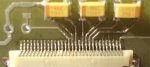
i've checked the usual suspects - there are no solder bridges under the LCD connector and there are no floating pads. i've had the micro generate 0x55 on the data and control ports, i probed the pins on the topside of the LCD connector with the LCD plugged in. i could see alternating 1s & 0s on every other pin - therefore every pin is driven and there are no solder bridges between neighboring pins.

as for timing, at first i was running at 8MHz, then i tried slowing down and running at 1MHz. now i've got delays sprinkled in during /write pulses and between writes. originally i was lifting /CS between writes, i found a user here that just left it low from first use and it seemed more efficient.

the LCD is connected as so:
Code:
   LCD pin           Mega128 pin
    IRS              tied to +5V    -- internal V5 resistor divider in use
    C86              tied to +5V    -- set I/O mode to 6800
   /CS1              PORTF.3        -- chip select, active low
   /RST              PORTF.4        -- reset, active low
   /A0               PORTF.5        -- command or data indicator - low indicates cmd
   /WR               PORTF.6        -- write, active low
   /RD               PORTF.7        -- read, active low -- kept high in normal operation
    D0               PORTA.0
    D1               PORTA.1
    D2               PORTA.2
    D3               PORTA.3
    D4               PORTA.4
    D5               PORTA.5
    D6               PORTA.6
    D7               PORTA.7

    V1-5             1uF cer cap to GND
    VR               no connection
    VOUT             10uF tant cap- to GND and CAP3-
    CAP3-            10uF tant cap- to GND and VOUT
    CAP1+            10uF tant cap+ to CAP1-
    CAP1-            10uF tant cap- to CAP1+
    CAP2-            10uF tant cap- to CAP2+
    CAP2+            10uF tant cap+ to CAP2-
the method i am currently trying to initiate the device:
Code:
      // set up LCD ports - defined in glcd.h
   LCD_CTRL_DDR = 0xF8;
   LCD_DATA_DDR = 0xFF;

      // start up with /RESET low
   LCD_CTRL = ~( LCD_RST );
   LCD_DATA = 0x00;

      // hold reset state for some time
   _delay_us(200);
   LCD_CTRL |=   LCD_RST;

      // drop chip select - held low as it's the only device on this bus
   _delay_us(200);
   LCD_CTRL &= ~ LCD_CS;
   _delay_us(200);

      // write reset command
   LCD_DATA = RESET_DISPLAY;  // 0xE2
   LCD_CTRL &= ~ LCD_A0;
   _delay_us(50);
   LCD_CTRL &= ~ LCD_WR;
   _delay_us(50);
   LCD_CTRL |=   LCD_WR;
   _delay_us(50);

      // write lcd bias - this was used successfully on previous board
      //    i've tried 1_7    // 0xA3
   LCD_DATA = LCD_BIAS_1_9;   // 0xA2
   LCD_CTRL &= ~ LCD_A0;
   _delay_us(50);
   LCD_CTRL &= ~ LCD_WR;
   _delay_us(50);
   LCD_CTRL |=   LCD_WR;
   _delay_us(50);

      // adc select normal
   LCD_DATA = ADC_SELECT_NORMAL; // 0xA6
   LCD_CTRL &= ~ LCD_A0;
   _delay_us(50);
   LCD_CTRL &= ~ LCD_WR;
   _delay_us(50);
   LCD_CTRL |=   LCD_WR;
   _delay_us(50);

      // 
   LCD_DATA = COM_OUTPUT_NORMAL; // 0xC0
   LCD_CTRL &= ~ LCD_A0;
   _delay_us(50);
   LCD_CTRL &= ~ LCD_WR;
   _delay_us(50);
   LCD_CTRL |=   LCD_WR;
   _delay_us(50);

      // i've tried a range of values here...  no luck
   LCD_DATA = V5_RESISTOR_RATIO; // 0x21
   LCD_CTRL &= ~ LCD_A0;
   _delay_us(50);
   LCD_CTRL &= ~ LCD_WR;
   _delay_us(50);
   LCD_CTRL |=   LCD_WR;
   _delay_us(50);

      // set contrast (electronic volume in technote and other docs)
   LCD_DATA = CONTRAST_SET;   // 0x81
   LCD_CTRL &= ~ LCD_A0;
   _delay_us(50);
   LCD_CTRL &= ~ LCD_WR;
   _delay_us(50);
   LCD_CTRL |=   LCD_WR;
   _delay_us(50);

      // initial contrast value
      //    i've treid a range of values, this worked on previous board
   LCD_DATA = CONTRAST_INIT;  // 0x20
   LCD_CTRL &= ~ LCD_A0;
   _delay_us(50);
   LCD_CTRL &= ~ LCD_WR;
   _delay_us(50);
   LCD_CTRL |=   LCD_WR;
   _delay_us(50);

      // power setup - trying stepped writes per advice in forum post
   LCD_DATA = 0x2C;  // 0x2C
   LCD_CTRL &= ~ LCD_A0;
   _delay_us(50);
   LCD_CTRL &= ~ LCD_WR;
   _delay_us(50);
   LCD_CTRL |=   LCD_WR;
   _delay_us(50);

   LCD_DATA = 0x2E;  // 0x2E
   LCD_CTRL &= ~ LCD_A0;
   _delay_us(50);
   LCD_CTRL &= ~ LCD_WR;
   _delay_us(50);
   LCD_CTRL |=   LCD_WR;
   _delay_us(50);

   LCD_DATA = 0x2F;  // 0x2F
   LCD_CTRL &= ~ LCD_A0;
   _delay_us(50);
   LCD_CTRL &= ~ LCD_WR;
   _delay_us(50);
   LCD_CTRL |=   LCD_WR;
   _delay_us(50);

      // turn the display on...
   LCD_DATA = DISPLAY_ON;  // 0xAF
   LCD_CTRL &= ~ LCD_A0;
   _delay_us(50);
   LCD_CTRL &= ~ LCD_WR;
   _delay_us(50);
   LCD_CTRL |=   LCD_WR;
   _delay_us(50);
so - does anyone see anything here? i can honestly say i'm stumped.

i've ported the code working from the old PCB (written for IAR) to avr-gcc on the new board. as far as i can see, the signals are all proper high / low and write timing should be very slow and stable. i'm seeing rise / fall times of about 15ns and the 'scope indicates the delays are being held as the code indicates. i've also tried shorter delays (which should be perfectly permissible down to reasonable execution rates) and i've tried cranking delays up to seconds between transitions...

none of this has started the internal charge pumps.

also - i've tried three LCDs - two new, one is a spare from when i built the first batch of boards years ago.

so - please tell me i'm missing something stupid :)

sorry for the long post - thanks for reading!
Looking for additional LCD resources? Check out our LCD blog for the latest developments in LCD technology.
 
In my usage of the display, I've never had any contrast with resistor ratio settings less than 0x25, and I usually use 0x26. Maybe you've seen my init settings, as I have posted them a few times in these fora.

I don't see any code reason why the charge pumps might not be active. Here are the voltage readings I see when the display is operating properly:
Code:
pin 17 (Vout)    -9.5v
pin 19 (cap1+)   2.5v (VOM reading of square wave)
pin 20 (cap1-)   -2.3v (VOM reading of square wave)
pin 21 (cap2-)   -7.2v (VOM reading of square wave)
pin 22 (cap2+)   2.5v (VOM reading of square wave)
pin 23 (V1)      3.9v
pin 24 (V2)      2.6v
pin 25 (V3)      -2.6v
pin 26 (V4)      -3.6v
pin 27 (V5)      -4.7v
Sometimes I have seen problems with the charge pump output being low and drifting. This was found to be due to leakage in the caps, either bad caps, or residual flux under the smd caps. Now I take great care that the row of caps is well cleaned after soldering.

The only thing that I can suggest at this point is connection problems with the caps, either at the zif socket or the caps, or some other wiring error.
 

pwhitt

New member
In my usage of the display, I've never had any contrast with resistor ratio settings less than 0x25, and I usually use 0x26. Maybe you've seen my init settings, as I have posted them a few times in these fora.
thanks for the info!

yes - i've seen your posts, thanks. you're one of the few people that come up in a google search for solutions to using this LCD.

i'll take a stab at populating another board and see how it comes out.

what are your thoughts on using larger caps on the CAP pins? in the previous generation of this board, i misread one of the app-notes (i think it was a poor print) and the author had placed 0.68uF caps there, but printed .68uF and what i read was 68uF. so i went out of my way to find a 68uF ceramic. the first one i built worked right off, but then i found i could reliably use 10uF or less...

anyway - could it be I need higher capacitance there? are the tantalum ESRs going to be too high?

when i write a while loop to draw a checkerboard (i do this many times over so i can observe it), i see what looks like switching activity on the CAP pins. they only swing +/-2V though. i just can't get why i see potentials that should be negative floating near +5V that bleed down when i measure them...

i'll also try cleaning the board really well before populating with new caps... we'll see.
 
what are your thoughts on using larger caps on the CAP pins? in the previous generation of this board, i misread one of the app-notes (i think it was a poor print) and the author had placed 0.68uF caps there, but printed .68uF and what i read was 68uF. so i went out of my way to find a 68uF ceramic. the first one i built worked right off, but then i found i could reliably use 10uF or less...

anyway - could it be I need higher capacitance there? are the tantalum ESRs going to be too high?
In my designs, I use 3 of 4.7 uF for Vout (cap3), cap1, cap2, and 5 of 1.0 uF for the V string filters. I've seen designs that use yet smaller values, so you shouldn't need anything more than what I use. BTW, I'm using the 3x step-up circuit and a 5 v supply.
i just can't get why i see potentials that should be negative floating near +5V that bleed down when i measure them...
The only reason I can think of is very high resistance connections, or perhaps something wrong with a ground or supply connection to the caps.
i'll also try cleaning the board really well before populating with new caps...
Actually, cleaning the board after populating is more important.

Perhaps a good in-focus (i.e. macro) photo of the ZIF/cap area will show something.

Here is a photo of one of my boards:
https://forum.crystalfontz.com/attachment.php?attachmentid=1497&d=1226606443
which is from this thread (the 51553 is virtually the same as 51320 except for pin numbers), showing the same parts values I use:
https://forum.crystalfontz.com/showthread.php?t=6093
 

pwhitt

New member
hi cosmicvoid!

well, i finally got around to some more testing... still no luck.

i attached a jpg of the header, and although they can be a bother, i've soldered much worse successfully. i really doubt it's leakage current - i mean, we're at 9V... also - i've done some playing around and found something odd. if i open and close the clasp on the header a handful of times, i see the switcher start and the appropriate voltages are generated by the charge pump.

so - the hardware on the board is capable of providing the voltages. i've also run the ribbon cable from a working board to the one i've used here and it works... also, the other working lcd does not work on this board, however behaves the same way if i play with the header clasp.

let me explain further - if i just power the pcb and have the micro produce nothing, but hold the bus in an idle state (out of reset) then open and close the clasp a handful of times, i see the charge pump start up. in the meantime, since my last test code post, i've ported the rest of my old code from IAR and have the following routines to initialize the screen:

Code:
void lcd_init(void)
{
   lcd_hard_reset();

   lcd_hard_reset();
   lcd_write(CMD,RESET_DISPLAY);
   lcd_write(CMD,LCD_BIAS_1_9);
   lcd_write(CMD,ADC_SELECT_REVERSE);
   lcd_write(CMD,COM_OUTPUT_NORMAL);
   lcd_write(CMD,V5_RESISTOR_RATIO);
   lcd_write(CMD,CONTRAST_SET);
   lcd_write(CMD,CONTRAST_INIT);
   lcd_write(CMD,(POWER_CTRL_SET | V_REGULATOR | V_FOLLOWER | BOOSTER_CIRCUIT));
   lcd_write(CMD,DISPLAY_ON);
}


void lcd_hard_reset(void)    // toggles reset pin - does not write reset command
{
   LCD_ASSERT_RESET();
   _delay_us(20);
   LCD_DEASSERT_RESET();
}


void lcd_write( unsigned char data_type, unsigned char data )
{
   if( data_type == CMD )
   {  LCD_ASSERT_CMD();
   }
   else
   {  LCD_ASSERT_DATA();
   }
   LCD_DATA = data; // let data settle long before strobing
   LCD_SELECT();
   LCD_ASSERT_WRITE();
   LCD_DEASSERT_WRITE();
   LCD_DESELECT();
}
any ideas??
 

Attachments

if i just power the pcb and have the micro produce nothing, but hold the bus in an idle state (out of reset) then open and close the clasp a handful of times, i see the charge pump start up.
I am baffled by this. If the micro "produces nothing" (held in reset, or a loop?), then how can the SED1565 charge pumps be enabled?? They should only be running when the init code turns them on. Who knows what kind of signals the open/close of the connector provides to the display; I'd be reluctant to do that, myself.

As for your code, you don't supply the detail for the
Code:
   LCD_ASSERT_WRITE();
   LCD_DEASSERT_WRITE();
macros, and there are no obvious delays, so I'm wondering what the strobe width is, which would be dependent on your cpu clock speed, etc.

The photo doesn't show the other 5 caps. Are they on the other side of the ZIF connector? As for leakage at "only 9 volts", we're talking microamps here (megohms), as the whole bias chain is relatively high impedance.

Sorry I can't offer any better advice.
 

pwhitt

New member
I am baffled by this. If the micro "produces nothing" (held in reset, or a loop?), then how can the SED1565 charge pumps be enabled?? They should only be running when the init code turns them on. Who knows what kind of signals the open/close of the connector provides to the display; I'd be reluctant to do that, myself.
well, i was looking at a problem on two boards that was linked to only a few variables, the flex connector being one of them (perhaps bad, not making contact, etc). so i wrote a loop that waited a couple seconds and reinitialized the screen and displayed a checkerboard. i opened and closed the header clasp while monitoring one of the caps and voila - the internals started pumping 9V. it would do this until the next reinitialization came along, then it would stop on the reset (not command, but reset pin toggle) and not start again.

so i suspected something was up with my code and started repeating this, pruning steps from my initialization process until i came down to what was basically - set-up-the-ports; while(TRUE){}; even while running that code, the pumps will start up after opening/closing the header clasp a handful of times...

i'm as baffled by this, but it does demonstrate that the hardware on the boards will function when the charge pumps start.

re the macros for assert / deassert:
they're just renamed from the original post - assert clears the bit (LCD_CTRL &= ~ LCD_WR), deassert sets it (LCD_CTRL |= LCD_WR).

re clock speed and strobe width - here is the background:
my first boards (the ones that worked a few years ago) were operating with an external 14.7356MHz clock and outside of the /reset being a prolonged width of a few us, all other steps were not delayed - so pulses of ~200-500ns on R/W and writes ocurring at about ~1000ns will work on this board. the datasheets i've looked at indicate a write pulse can be 60ns.

that being said, the new board is running an internal 8MHz clock and i've sprinkled delays liberally throughout, ranging from 1us to 200ms. in no cases did the initialization work.

so the conclusion i drew from this is that i must have mapped the port incorrectly, or the pin assignment is wrong or i'm toggling pins in the wrong direction - something stupid. right? it has to be!

but:
i sat down with excel and made a table of the interface bits and what they were mapped to and how they should toggle to initialize the screen. then i put a "while(TRUE){};" after each change in the control or data port to the LCD and probed each pin on the header and verified that at the end of each transition, the bits were in the correct state. it all agreed. and i was probing the top of the connector - not the traces on the PCB - indicating all the pins are connected correctly...

the really frustrating thing is that the code worked - i just changed a few things to port from IAR to WinAVR...

another problem is that my 'scope at home is an *old* tek 2246 and i have no way to trap the initialization sequence all at once. i'll put it on a mixed signal scope at the office if when i get the time - it might be a week or so before i get around to that...

i'll put up that table of bits and verification i ran when i get to it. perhaps you'll point out i've been doing something wrong all along and it's a fluke the original board worked - that'd be funny.
 

pwhitt

New member
ok - here's some more detail... i made this table up and then set up a main loop similar to this:
Code:
    // set up LCD ports - defined in glcd.h
LCD_CTRL_DDR = 0xF8;
LCD_DATA_DDR = 0xFF;

    // start up with /RESET low
LCD_CTRL = ~( LCD_RST );
LCD_DATA = 0x00;

_delay_ms(200);

LCD_CTRL |= LCD_RST;

while(TRUE)
{
   LCD_DATA = RESET_DISPLAY;
   LCD_CTRL &= ~ LCD_A0;
   _delay_us(50);
   LCD_CTRL &= ~ LCD_SELECT;
   _delay_us(50);
   LCD_CTRL &= ~ LCD_WR;
   _delay_us(50);

   while(TRUE){};   // <- i'd stop it and make a measurement here

   LCD_CTRL |=   LCD_WR;  // select and A0 beyond this point can remain low - right?
                                     //  i've also tried toggling A0 and CS back high at this point, CS toggling first
   _delay_us(50);

   while(TRUE){};   // <- i'd stop it and make a measurement here


   LCD_DATA = LCD_BIAS_1_9;
   // same procedure repeated here

   LCD_DATA = ADC_SELECT_REVERSE;
   // same procedure repeated here

   LCD_DATA = COM_OUTPUT_NORMAL;
   // same procedure repeated here

   .... on and on through the initialization...
}
for completeness - i've also pasted below the commands i'm using and pin mapping as well as the results of the measurements i made... just in case someone sees something i overlooked.

Code:
*************** COMMAND TABLE *******************

COMMAND	             D7 D6 D5 D4 D3 D2 D1 D0

DISPLAY_ON            1  0  1  0  1  1  1  1
DISPLAY_OFF           1  0  1  0  1  1  1  0
DISPLAY_START_LINE    0  1  n  n  n  n  n  n
PAGE_ADDRESS_SET      1  0  1  1  n  n  n  n
COLUMN_ADDR_HIGH      0  0  0  1  a  a  a  a
COLUMN_ADDR_LOW       0  0  0  0  a  a  a  a
ADC_SELECT_NORMAL     1  0  1  0  0  0  0  0
ADC_SELECT_REVERSE    1  0  1  0  0  0  0  1
DISPLAY_NORMAL        1  0  1  0  0  1  1  0
DISPLAY_REVERSE       1  0  1  0  0  1  1  1
ALL_POINTS_ON         1  0  1  0  0  1  0  0
ALL_POINTS_OFF        1  0  1  0  0  1  0  1
LCD_BIAS_1_9          1  0  1  0  0  0  1  0
LCD_BIAS_1_7          1  0  1  0  0  0  1  1
READ_MOD_WRITE        1  1  1  0  0  0  0  0
END                   1  1  1  0  1  1  1  0
RESET                 1  1  1  0  0  0  1  0
COMMON_OUTPUT_NORMAL  1  1  0  0  0  *  *  *
COMMON_OUTPUT_REVERSE 1  1  0  0  1  *  *  *
POWER_CTRL_SET        0  0  1  0  1  *  *  *
                                     1
                                        1
                                           1
V5_RATIO_SET          0  0  1  0  0  r  r  r
CONTRAST_SET          1  0  0  0  0  0  0  1
CONSTRAST_VALUE       *  *  c  c  c  c  c  c


******** COMMAND SEQUENCE AND PIN MAPPING *******

PORTF BIT   7    6    5    4    3     PORTF VALUE
LCD CTRL    RD   WR   A0   RST  CS
     idle   1    1    1    1    1      0xFF
assert a0   1    1    0    1    1      0xDF
   select   1    1    0    1    0      0xD7
write data  1    1    0    1    0      0xD7
assert wr   1    0    0    1    0      0x97
hold wr     1    0    0    1    0      0x97
release wr  1    1    0    1    0      0xD7
deselect    1    1    x    1    1      0xFF

********* VALUES MEASURED ON HEADER *************
         PINS (IN ORDER ON HEADER)
            1     2    3    4    5    6   D0--7
            NC    CS   RST  A0   WR   RD
idle              1    1    1    1    1
assert a0         1    1    0    1    1
select            0    1    0    1    1
write data        0    1    0    1    1   pattern expected
assert wr         0    1    0    0    1
hold wr           0    1    0    0    1
release wr        0    1    0    1    1
deselect          1    1    0    1    1
release a0        1    1    1    1    1
hopefully this is useful to anyone else also using this lcd...

thanks for any info cosmicvoid! later today i'm going to try to read from the chip - i'll have to look that information up as to what status is available, but it might tell me something.
 
Top