Hello,
I've been looking around the internet here along with this board and have found people with similar issues to the ones I'm having. It's been haunting me for about a week now. Please keep in mind, that I am new to this controller. I have programmed this ATMEGA324P in the past with an LC7981 controller and no problems.
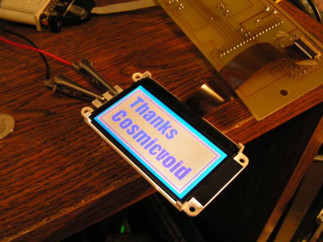
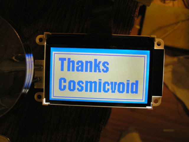
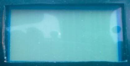
My Optrex F-51553 is delivering weird results. When I try to display an image of any kind, I get a screen that is either made up of random lines (vertical or horizontal) or a random crosshatch pattern. The thickness of the line varies.
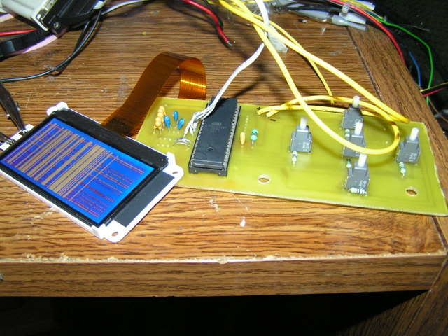
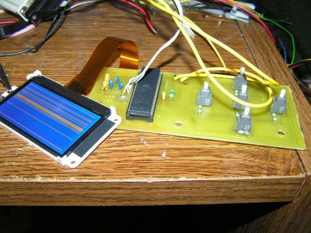
Right after I initialize, if I want to display all points on or all points off, command 10, it works fine and produces the results I expect.
MCU: ATMEGA324P
LCD: F-51553
I am using a 3 charge pump design shown here:

I've tried a few different routines to initialize the LCD. First is taking from the datasheet
Second is cosmicvoid
And the third was Graphical Alarm Clock by Matt Meerian, using the ATMEL ATMEGA32
My command LCD function is as follows (I found based on reading here that if I hold the CS1
pin low all the time the results are more consistent):
And finally, I've modified my write sequence to display either on and off by means of loops
I've referenced information here from the following posts:
https://forum.crystalfontz.com/showthread.php?t=3619
https://forum.crystalfontz.com/showthread.php?threadid=3808
https://forum.crystalfontz.com/showthread.php?t=3808&highlight=optrex
and website:
Matt Merian's Alarm Clock using ATMEGA32
http://www.geocities.com/matt6ft9/alarm_clock_index.html
Thanks,
Patrick
I've been looking around the internet here along with this board and have found people with similar issues to the ones I'm having. It's been haunting me for about a week now. Please keep in mind, that I am new to this controller. I have programmed this ATMEGA324P in the past with an LC7981 controller and no problems.
My Optrex F-51553 is delivering weird results. When I try to display an image of any kind, I get a screen that is either made up of random lines (vertical or horizontal) or a random crosshatch pattern. The thickness of the line varies.


Right after I initialize, if I want to display all points on or all points off, command 10, it works fine and produces the results I expect.
MCU: ATMEGA324P
LCD: F-51553
I am using a 3 charge pump design shown here:

I've tried a few different routines to initialize the LCD. First is taking from the datasheet
commandLCD(0xA2); // (11) LCD Bias Set
commandLCD(0xA1); // (08) ADC Selection
commandLCD(0xC0); // (15) Common Output State Selection
commandLCD(0x26); // (17) Setting Built In Resistance
commandLCD(0x81); // (18) a. Electronic Volume Control
commandLCD(0x20); // (18) b. Arbitrary Eelectronic Volume Constant
commandLCD(0x2F); // (16) Power Control Setting
Second is cosmicvoid
commandLCD(0xE2);
_delay_ms(0);
commandLCD(0xA1);
commandLCD(0xC0);
commandLCD(0xA2);
commandLCD(0xA6);
commandLCD(0x20 + 6);
commandLCD(0x81);
commandLCD(0x20);
commandLCD(0x28 + 4);
_delay_ms(0);
commandLCD(0x28 + 6);
_delay_ms(0);
commandLCD(0x28 + 7);
_delay_ms(0);
commandLCD(0xAF);
commandLCD(0x40);
commandLCD(0xB0);
commandLCD(0);
commandLCD(0x10);
dataDisplayLCD(0x0);
_delay_ms(10);
commandLCD(0x81);
commandLCD(48);
And the third was Graphical Alarm Clock by Matt Meerian, using the ATMEL ATMEGA32
commandLCD(0xE2); // (14) Reset
commandLCD(0xA1); // (08) ADC Select
commandLCD(0xC0); // (15) Common Output Mode Select
commandLCD(0xA6); // (09) Display Normal/Reverse
commandLCD(0x24); // (17) V5 Voltage Regulator Internal Resistor Ration Set
commandLCD(0x81); // (18) a. Electronic Volume mode Set
commandLCD(0x10); // (18) b. Electronic Volume Register Set
commandLCD(0x2F); // (16) Power Control Set
commandLCD(0x40); // (02) Display start line set
commandLCD(0xB0); // (03) Page address set
commandLCD(0x10); // (04) a. Column address set upper bit
commandLCD(0x00); // (04) b. Column address set lower bit
commandLCD(0xAF); // (01) Turn Display ON/OFF
commandLCD(0x1B); // (04) a. Column address set upper bit
commandLCD(0x81); // (18) a. Electronic Volume mode Set
commandLCD(0x30); // (18) b. Electronic volume register set
My command LCD function is as follows (I found based on reading here that if I hold the CS1
pin low all the time the results are more consistent):
void commandLCD(int lcdRegister)
{
PORTB |= 0b00010000; // nRD high
PORTB &= 0b11111011; // A0 low
//PORTB &= 0b11111110; // nCS1 low
PORTB &= 0b11110111; // nWR low
PORTD = lcdRegister;
PORTB |= 0b00001000; // nWR high
//PORTB |= 0b00000001; // nCS1 high
PORTB &= 0b11101111; // nRD low
}
And finally, I've modified my write sequence to display either on and off by means of loops
void dataDisplayLCD(int input)
{
int page = 0, col = 0;
for(page = 0; page < 8; page++)
{
commandLCD(0xB0 + page);
commandLCD(0x10);
commandLCD(0);
for (col = 0; col < 128; col++)
dataWriteLCD(input);
}
}
I've referenced information here from the following posts:
https://forum.crystalfontz.com/showthread.php?t=3619
https://forum.crystalfontz.com/showthread.php?threadid=3808
https://forum.crystalfontz.com/showthread.php?t=3808&highlight=optrex
and website:
Matt Merian's Alarm Clock using ATMEGA32
http://www.geocities.com/matt6ft9/alarm_clock_index.html
Thanks,
Patrick
Looking for additional LCD resources? Check out our LCD blog for the latest developments in LCD technology.


