Hi All,
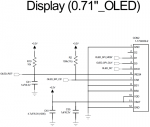
I attached a file that is schematics using CFAL4864A-071BW
I'd like to use '1.8V' logic level.
So, I connect to Vdd 1.8V.
Is it possible?
Refer Nets of that schematics.
+3.2V : 3.2V / 100mA
VDD_S : 1.8V / 200mA
SDA_2 : I2C Data
SCL_2 : I2C Clock
/OLED_RST : Connect to GPIO of MCU
Refer parts of that schematics.
CON2 : connector for CFAL4864A-071BW
That is for Wearable Device.
Review & Comment my schematics , ASAP.
Best Regards,
Inho Jeon.
Looking for additional LCD resources? Check out our LCD blog for the latest developments in LCD technology.
Attachments
-
15 KB Views: 672