Looking for a replacement LCD (16x2) for E-MU Sp1200

Deta!L

New member
I've taken some pictures, but the general idea is that the LCD is 16x2 and should be around 84x44mm. I don't see an EL-Panel or an inverter on this model so perhaps it's LED backlit-I don't know, but it's an old (circa 1994) drum machine.

the backlight gallery is here http://gallery.me.com/mrkauk#100108

and here is the CrystalFontz backlight I found that I thought might work, I'd like to have a different color than the original green/yellow.

http://www.crystalfontz.com/product/CFAH1602C-TMI-JT

do you think it would work? or would something be more suitable? also where can I find a replacement ribbon cable like the original? I've tried in the past and because there are so many solderpoints on those ribbons I usually end up destroying them.

Thanks in advance!

miKe

mrkauk@me.com
Looking for additional LCD resources? Check out our LCD blog for the latest developments in LCD technology.
 

CF Tech

Administrator
OK, I put your 84.98mm and 36.1mm into the parametric search, along with 16x2 characters:

http://bit.ly/85U1Ty

So it is likely that the CFAH1602C series will work:

http://www.crystalfontz.com/products/1602c-wt/

The Vo pin is analog and may need to be adjusted. If the original device has a "contrast" adjustment, that may be enough.

You will also need to do the math on the LED backlight and make sure current is limited properly. Since there is only one cable to your display, there will probably need to be some jumpers closed on the LCD module to route the power from the ribbon cable over to the backlight. If everything else on the module works, then we can get the support tech involved to tell you what resistors need to go on what pads.
 

Deta!L

New member
cool, thanks for your help.

I'm going to order the blue one then. Do you also sell the ribbon cable I need?

There is no contrast adjustment on the machine.

There are already jumpers on the LCD you guys are selling? I'm only familiar with the jumpers on a disk drive.

I'm guessing you're saying that since the two holes aren't used I have to somehow convert the flow of power from those spots to the display? Sorry, I"m an intelligent person when it comes to Finance/Marketing/Business, not so much with electronics. I'll find out how much power is coming from the machine through the cable and try to "do the math"...how would I be able to limit that power since it comes from the cable straight to the display?

confused...guess I'll order the display and call you guys when I get it...should be fun :p
 

CF Tech

Administrator
Please call in first and let the tech help you out with the resistors. We can solder them on for you and possibly pre-set the contrast, which we have a lot of experience doing :) We can probably also put a connector on there for you too.

Is there something wrong with the existing LCD?

Do you have a volt meter? Can you measure the voltage on between 1 and 2 when it is in operation?


Attachments

Deta!L

New member
Ugh, I already ordered one and have it in hand! Thanks for the faaaast shipping!

My father has a volt meter I can borrow, so I should have that answer tomorrow...wish I would have saw this before I ordered..no biggie though.

Thanks again for your help.
 

Deta!L

New member
okay, looks like 5 volts (4.8 volts on a radio shack voltmeter)

let me know what I need to do next, if anything, before I hook this thing up

thanks!

miKe
 

Deta!L

New member
Cool, thank you.

I just got a pack of 1/8 watt 100 ohm resistors from Radio Shack. I'll solder it across 1 and 2 when I get home, and that should be it huh?

Is there a way to adjust the contrac on the backlight itself or do you need a controller to do it? Thanks.
 

CF Support

Administrator
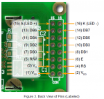
You'll actually want to open JP15 and JP16, and then close JP1 and JP2 (one or both (if your resistor is half the value you need) of which with your current limiting resistor). Afterward you should be set up to run the backlight off pins 1 and 2, current limited.
 

Deta!L

New member
You'll actually want to open JP15 and JP16, and then close JP1 and JP2 (one or both (if your resistor is half the value you need) of which with your current limiting resistor). Afterward you should be set up to run the backlight off pins 1 and 2, current limited.
Without looking at the display, Im assuming JP15 and 16 are labeled on the back? What do you mean by open and close? Solder? Or something else

thx for holding my hand through all of this
 

Deta!L

New member
well, I just screwed the pooch...I can't remove the old ribbon cable, I knew I couldn't get it-as I've fubar'd them before, but I just reaffirmed the fact.

can you guys sell me another display that's ready to go already?

AND

in addition, I'd like to also order a spare ribbon cable to install in the one I just did if that is possible...

please email me at mrkauk@me.com and let me know how I can place the order?

thanks for your time
 

Deta!L

New member
PS your help wasn't a total loss, I believe I have the display ready to install ( I did just as you all instructed) I just need a new ribbon cable :confused: because I couldn't remove it from the old display (and broke it trying) :mad:
 

CF Tech

Administrator
We do not have a cable like that. But Digi-Key can help you out. You would need:

http://search.digikey.com/scripts/D...=hp_go_button&KeyWords=h3aas-1406m-nd&x=0&y=0

That is a 14-pin 6" long female connector to female connector cable. Make sure 6" is long enough.

Then you would need a 14-pin header like:

http://search.digikey.com/scripts/D...ang=en&site=us&keywords=sam1036-07-nd&x=0&y=0

or if there is a clearance issue behind the board you might want to use:
http://search.digikey.com/scripts/D...ang=en&site=us&keywords=sam1037-07-nd&x=0&y=0

They have a minimum order, so you might as well get 2 of each ;)

The header would solder into the LCD, then the cable would plug onto both connectors. Just make sure the red stripe starts and ends on the same places it used to.
 
Top