LED backlighting spec

v8dave

New member
Hi,

Anyone know what the LED backlighting spec for the CFA320240F-T-TS display is?

There is no information in the datasheet other than the connection details. I need to know the forward voltage of the LED's and the optimal current draw for best screen brightness.

Thanks
Dave...
Looking for additional LCD resources? Check out our LCD blog for the latest developments in LCD technology.
 

CF Support2

Administrator
Dave:

The specs are in there, but with the preliminary datasheet we currently have, they are somewhat buried on the dimension / diagram page.

There are a total of 6 LEDs in the backlight - with two legs of 3 LEDs in series. The forward voltage for each LED is +3.3v, so you will need about +9.9v on each anode line. Your Iled (current) is about 12.5mA. You can of course, adjust these values as needed for your applications. The max forward voltage is +3.5v and we would not recommend pushing more than the 12.5mA through the LEDs.
 

v8dave

New member
Still can't find it on my datasheet!! :)

Thanks for the information though, this is just what I was looking for. I'll need to design a step up power supply for the LED backlighting as my board only has 3.3V available.

Cheers,
Dave...
 

CF Tech

Administrator
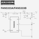
Please consider a current feed-back LED driver like the NCP5007 or FAN5333. These are designed to control the current, which is what you need to control.

If the voltage works out, you would want to hook all 6 LEDs in series and drive them with one controller.

(see Acrobat page 7 of the CFA320240F-T-TS datasheet, labeled "Page 6 of 18")

3.3v * 6 = 19.8v

The NCP5007 is good for "Vout to 22V Output" so it would work, but be close to its limit.

The FAN5333 is good to 30v, so that might be a safer choice.

With either of these, you do not need the traditional current limiting resistor:


Attachments

v8dave

New member
Excellent. Cheers for that. I have found the NCP5007 available from stock at my usual supplier so I will look at using that to drive the LED.
 

CF Tech

Administrator
You will be really close with 6 LEDs on the NCP5007. If the LEDs are just 3.4v forward voltage (which is very possible), the output voltage will need to be 20.4v. That might make them dim or worse, put the NCP5007 into protective reset, which I think can only be recovered by a power cycle.

You could use two NCP5007 (one per side) but a higher voltage solution like the FAN5333 would be more elegant.
 

v8dave

New member
Yeah, I just downloaded the datasheet and noticed the 20V limit. According to the datasheet removal of the EN signal should reset the driver but it also states that power removal may be required. Belt and braces I guess?

The trouble with the FAN5333 is no stock at present but I will fire off an email and see what the lead time is.

What I can do is build the PCB for both devices and then choose to populate the one I need based on what device I can get. I have loads of space on the display PCB to do this anyway.

Cheers,
Dave...
 

bigchuck33

New member
How did you calculate the value of "R" in the FAN5333?

The datasheet says Iled = Vfb / R.

We know Iled = 12.5mA
What is Vfb?
 

snorlax

New member
I'm planning to layout the backlight circuit soon for my CFAF320240F-T-TS and need some clarifications.

I have the A version of FAN5333(A) and a good 10 uH inductor ready to go.

How do you choose between the A version and the B version of FAN5333? Is it just a matter of preference of resistor I'd need to use? I don't know what the difference in feedback voltage really means, other than the fact that it affects the resistor I need to use.
 
How do you choose between the A version and the B version of FAN5333? Is it just a matter of preference of resistor I'd need to use? I don't know what the difference in feedback voltage really means, other than the fact that it affects the resistor I need to use.
Seems to me like there's not much difference between the two feedback voltage choices; I can't imagine why they chose to offer those values. Yes, it only affects the resistor you need.

For the 'A' version (110mV reference), you will need a 8.8 ohm resistor for 12.5 mA LED current. You could run both LED strings in series.
 
Top