CFAH4004A-YYH-JP Initialization

glsdean

New member
Got Your Message

Hi Cosmicvoid,
I'm in SoCal, in the High Desert area, about halfway between LA and LV. We're in the same time zone. I did write and run a test program to toggle the Basic Atom pins one at a time and it ran successfully, that is the pins toggled high/low for the correct period of time. I have also checked for shorts on the headers and connectors on both the LCD and Basic Atom and found no shorts - at least I soldered everything correctly. If you have any specific wiring issues you think I should check, even the "dumb ones", please let me know. I'm reticent to consider buying an o-scope, at this time, because the cost for a budget-priced scope is about what I already have in the project. For that amount, I figure it would be more cost-effective to replace the Basic Atom/CFAH4004A combo, that doesn't work, with a combo that does work. I'll take a look at the ZiLog unit.

Concerning learning "C", I'm probably making a bigger issue of it than it really is. In my previous attempts at "C" I was really thrown off by the grammar and syntax, it seemed very obscure. If I were to pick up a primer on "C", to get me off to a fresh start, is there one you would recommend?

Having the box connected to an AC outlet isn't a problem, the only units that are changing that I really want to monitor are the UTC time/date.
Best Regards
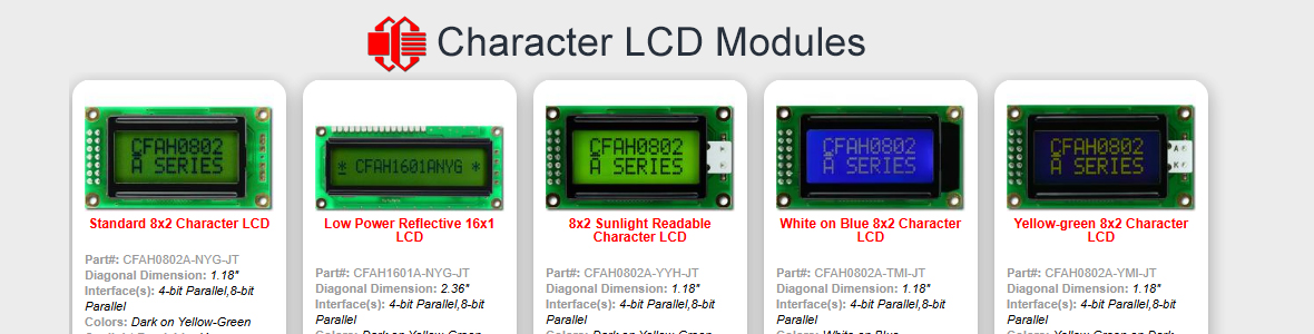
Looking for additional LCD resources? Check out our LCD blog for the latest developments in LCD technology.
 

CF Support2

Administrator
For learning C - a book I found rather handy was "The Absolute Beginners Guide to C" by Greg M Perry. It really works from the ground up. The last version was 1994 (tell you how much C has changed). It is in and out of print and I belive it's "2nd Edition" now. Here are the particulars:

Publisher: Indianapolis, Ind. : Sams Pub., ©1994.
ISBN: 0672305100 : 9780672305108

Amazon has it in stock: (see a used one for about $10.00 shipped)

http://www.amazon.com/Absolute-Begi...4238327?ie=UTF8&s=books&qid=1188425111&sr=8-1
 
I remember that you toggled the pins, but did you check the result at the display?
... any specific wiring issues you think I should check ...
I'm thinking that you should verify that each particular port pin is actually connected to the correct input on the LCD. Maybe you could post your wiring list.

The next conclusion would be that the display itself has a problem. Do you have any other HD44780 type character-mode displays (of any size/config) lying around, that you could try?
 

glsdean

New member
Wiring Diagram

Hi Cosmicvoid,
I'm attaching the microcontroller/LCD wiring diagram i used. Hope it is understandable. I have verified that the correct pins from the Basic AtomPRO are wired to the correct pins of the LCD. The wires are color-coded, so its pretty easy to that the wiring is correct. I only have the one CFAH4004A to work with and do not have any other HD 44780 displays to work with. Because, the CFAH4004A is at least showing its hardware init and I'm getting voltages from the Basic Atom Pro pins I've assumed, maybe falselly, that both were operating OK and that all the problems are software related.

I could buy another CFAH4004A to see if that's the problem, but at this point I'm more prone to try the non-PRO version of the Basic Atom to see if that's the problem. The Basic Atom PRO is built around the Hitachi H8/3664 chip whereas the Basic Atom 24 is built around the PIC micro 16F876 MCU. As I've mentioned before, some Basic Atom users report that the Basic Atom PRO is "quirky", so I'm really wondering if switching to the less "quirky" PIC based controller might solve the problems. Let me know what you think?

I'll see if I can find a copy of "The Absolute Beginners Guide to C", otherwise I was thinking about the Dummies Guide to C/C++.
Best Regards,
glsdean
 

Attachments

... the CFAH4004A is at least showing its hardware init ...
You must mean that rows 1 and 3 are all dark cells, which is the symptom of lack of init. Oh, I forgot to mention, you should tie D0~D3 low if you are using the 4-bit interface. Some people claim it doesn't matter, but I think it does. Then try the code again.

As far as switching to the Atom non-pro, that's up to you. I can understand that you want to make the most of your investment with that product line. If it was me, after seeing the crappy documentation, I'd be running away from it. If you stick with the Atom, then you won't need to learn C, either. As I recall, the 24 pin BASIC-type controllers (Atom, Stamp, etc) do not feature line by line debug/breakpoints/single-stepping thru your program, like the SBCs do, and cost more than some SBCs to boot.

Its unfortunate that you don't have access to test equipment, to verify the signal timing. But whatever hardware you choose, if you still have problems, I am willing to suggest things to try. But you know.... it's hard to be helpful with code/hardware that I can't test.
 

glsdean

New member
Listening to your advice

Hi Cosmic,
Yes, I mean rows 1 and 3 of the LCD show dark cells, which I've interpeted as meaning that the LCD is not initialized but the hardware is working. Could you explain how to tie D0 ~ D3 low? Would that be just sending a "Low" command to pins D0 ~ D3 during the initialization or is that a physical connection.

I haven't given up on scraping the Basic Atom yet, but think I would be remiss for not trying the Basic Atom 24 before I toss all the past effort away. Replacing the module isn't a big cost anyway.
 

glsdean

New member
R/W Pin

Hi Cosmic,
Taking D0 ~ D3 to ground will require soldering a header to the ground contacts on the microcontroller board. That's not a problem, so long as I have the parts. However, I've also seen mention that the if the LCD R/W pin isn't being used for read functions (which applies to this project) it should be grounded. Should I also take the R/W pin to ground?
 
Grounding D0~D3 can be done right at the LCD terminals, with short wires, and not connected to the microcontroller at all. You have left D0~D3 unconnected currently, right?

As for R/W, the most efficient way to regulate the timing of the commands to the LCD is to use the busy flag to determine when the LCD controller is ready for another command. That would require R/W to be dynamically controlled by an I/O pin. This raises the question about how the Atom LCDWRITE function works. Does it automatically check the busy flag prior to the write operation? The documentation does not even hint about that issue. That could only be determined by watching with a scope, as I said previously. Without knowing the answer, I, personally, would not even consider using the Atom. Sorry for rambling, does that answer your question?
 

glsdean

New member
Oscilloscope Features

Hey Cosmicvoid,
Just a question. If I go ahead a purchase an O'scope to test the microcontroller output to the LCD, what features must the O'scope and probes have to run the tests?
Best Regards,
glsdean
 
Wow, that's hard to say. Is it just for this project, or maybe for faster projects in the future also? I'll pick some numbers out of the air, and you see if you can afford to buy one. I am assuming a digital scope, so waveforms can be 'frozen' and stored. I'll also assume a USB scope, using a PC as the host/display, to keep the cost sane.

2 channels
25 MHz bandwidth min
100 MSamples/sec min

Search Google for "USB oscilloscope". I found several interesting ones for $700-800. But the most bang for the buck I found was (from China) this, for $329:
http://www.embedinfo.com/english/product/DS2300.asp

Some others:
http://www.teampctechnology.com/product_detail.php?id=481
http://www.picotech.com/picoscope-specifications.html
 

glsdean

New member
O'scope

Hi Cosmicvoid!
Attached file is a copy of the flyer/specs for the USB PC Oscilloscope I ordered. I expect delivery in the next 10-14 days. While we're waiting, would you be thinking about what tests need to be performed and let me know what I will need to check. Hope to receive the Basic Atom 24-M this week. If it arrives in time I'll test it with the code segments you've sent and see if it responds differently than the Basic Atom Pro.
Best Regards,
glsdean
 

Attachments

Ha, that USB scope is sooo cheap that it's scary. It looks like it should be able to show you what you need to see.
... Hope to receive the Basic Atom 24-M this week. If it arrives in time I'll test it with the code segments you've sent ...
And what happens if it doesn't arrive in time? Is there a deadline?

As for what tests need to be performed, you should look at the E signal, to see the pulse widths and time between pulses. Trigger on the rising edge of E. On the other channel, see what RW and RS are doing while E is active. Just to give you a sample, I'm attaching some annotated scope traces I captured from my Zilog board, driving a graphic LCD (CFAG128128).
 

Attachments

glsdean

New member
Back Again

Hi Cosmicvoid,
It's been a few days, but I've been tied-up with regular "work". Thanks for your reply to my question about what to check with the o'scope and the screenshots. Since I last replied, I grounded DB0~DB3 on the LCD, received the BasicMicro 24 microcontroller, and received the o'scope. Grounding DB0~DB3 and replacing the BasicMicro PRO with the BasicMicro 24 had no effect on getting the CFAH-4004A to respond - still only showing black boxes on rows 1-3. Yes, I made sure to use the code and compiler designed for the BasicMicro 24 - it is different from the code and compiler for the BasicMicro PRO.

I did have a chance to "play" a little with the o'scope during the past weekend and can confirm that pulses are coming from both enable lines. I'll check the pulse width and timing this weekend along with examining what's happening concurrently with the E, RegSel, and R/W lines. Will try to save screenshots that I can post for you to examine.

Considering that pulses are coming accross the E lines, replacing the microcontroller, and grounding the DB0~DB3 pins had no effect on the LCD responding, do you think there's a chance the LCD is "bad". It just seems that with all these changes, there would have been some change in the LCD display.

Best Regards,
glsdean
 
... do you think there's a chance the LCD is "bad". It just seems that with all these changes, there would have been some change in the LCD display.
It is definitely suspicious, but too soon to say the LCD is bad. I will be interested to see the scope traces during the init phase; that should tell a more complete story.
 

glsdean

New member
Init-phase Traces

Hi Cosmic,
O'scope traces during the lcdwrite phase don't seem to be a problem because the program is looping through the write commands. However, the lcdinit commands only run once (for a very short time) at the start of the code. Should I include the lcdinit commands in the looping section of the code in order to "see" them?
Best Regards,
glsdean
 
Should I include the lcdinit commands in the looping section of the code in order to "see" them?
You could do that, as a last resort. I'd assume that your scope has a "single trace" mode, where it captures one bufferful when triggered, and then stops (instead of continuously re-triggering).

Then, each time you reset the cpu, you can grab the init section. Play with the H time base, to spread out the area of interest. Use one of the E signals as the trigger, and only deal with one of the controllers, until we figure out whats going on.

I'm not sure why you would ever need a "looping" section, unless you don't have a single trace feature. Do you have a delayed time base (delays the data capture until a chosen amount of time after the trigger)? I really didn't pay close attention to your scope's features.

Afterthought: I've got a CFAH1202 sitting around unused. I could loan it to you, as an alternate display to test with. PM me if you want me to drop it in the mail.
 
Last edited:

glsdean

New member
Initial Scope Traces

Hi Cosmic,
I have some initial o'scope traces I would like you to take a look at and give me your opinion as to what is going on. However, there seems to be a problem with the Forum database and I cannot post them. As soon as the Forum's technical issues are resolved, I'll post the traces. In the meantime, I follow your suggestions about single trace mode and see what I get.
Best Regards,
glsdean
 

glsdean

New member
Initial Scope Traces

Hi Cosmicvoid,
Attachment shows initial o'scope traces for Enable, R/S and R/W pulses during LCDWRITE comannd. Please review and let me know what you see. I've run additional traces since these for the lcd initialize commands available in BasicMicro syntax and am concerned about the waveforms that I see from the R/S pin, specifically the waveform appears to be sinusoidal with spikes at the leading and trailing edges of the Enable pulses. I would have expected nice square wave pulse from all pins. Will take some more traces and send them for review.
Best Regards,
glsdean
 

Attachments

Top