CFAG320240C-FMI-T .... Doesn't work with PIC

Tylerman

New member
Hi,
I have a LCD Graphic CFAG320240C-FMI-T and I try to initialise and write some dot on the screen and it doesn't work... I don't know if it's that the LCD is bad or my code .... A person can help my please. I have spend a lot of time and it don't working..

Thanks Yves
Looking for additional LCD resources? Check out our LCD blog for the latest developments in LCD technology.
 

cmp241

New member
PIC definitely work

Hey whats up the PIC is definitely compatible with your glcd. I am using this one, CFAG320240C-YMI-VZ, the only difference is the back light, so make sure you have it working. i am using the pic18f452 and the ccs compiler from www.ccsinfo.com. they have example codes. Anyways i used their example for the sed1335 controller and it worked perfectly i just had to change some pins and had to write a main function for it (a driver). Just put the init function and one of the fillscree function in the main function. If the attachment doesn't help than i do not know what will. Good luck write back and let me know how it goes or if you need more help.

Cedric
 

Attachments

JackOfVA

New member
CMP241 --

I've just started with an 18F458 and a CGAG320240C display, but I'm writing the code in Pascal.

Have you set the display for 8080 compatibility mode or 6800? The default jumper setting seems to be 6800 from what I can see and I believe it might be easier to make it play with a PIC in 8080 mode.

It's frustrating when you can't be sure if the problem is with the software or with the hardware connection. The data transfer timing diagrams in the SED1335 manual are not what I would call a model of clarity either.

Jack
 

cmp241

New member
Well according to the code posted above:

#ifndef GLCD_RD
#define GLCD_RD PIN_B5
#endif

The code is written for the the 8080.

pg. 7 of the CFAG320240CTMIVZ.PDF for interface description pin 4 is labeled E.

According to the Epson_S1D13305.pdf page 4, E corresponds to the 6800 and RD corresponds to the 8080.

I believe PICs are 6800. So I recommend you use 6800 mode.
But I am not certain what jumper default you are talking about. Can you point me to where I can see the settings. I have no experience with pascal, but heres another website with C code for the SED1335 controller.

Go to www.baso.no, click on programming in the left paenl, then click ImageCraft AVR, then look for the SED1330/SED1335 download but i am also going to attach it

Good Luck,
Cedric
 

Attachments

JackOfVA

New member
Cedric

I'll look at the further example code later today. Thanks for posting it.

The jumper that I am refering to is on the controller board. It's a zero ohm resistor, connected between +5V and Pin SEL1 of the S1D13305. This jumper is just below the 10 MHz resonator and is identified as JM. This position gives 6800 mode.

Moving the zero ohm resistor to the other pad will take SEL1 to ground, which gives 8080 mode.

Pin SEL2 is at ground.

JM is in 6800 mode as my board was built. This is consistent with the note at the top of the page of Section 7 of the CFAG320240C display data sheet, where it says "JM (right) short , for 6800 MPU family"

I believe the PIC will interface with the S1D13305 in either 6800 or 8080 mode, but that 8080 mode seems easier to implement. I'm a bit reluctant to move the jumper as working with small surface mount components isn't my favorite activity. Hence I'm first trying to get it playing in 6800 mode.
 

JackOfVA

New member
I can now report at least partial success. I can display text on the LCD, position it, clear it, etc.

The display is in stock mode, with the jumper default setting of 6800 compatibility.

I'll next start on graphics.

After reading CMP241's sample code, plowing through the data sheets a few more times and tinkering with some simple experimental code, I was able to make it work for text. I think graphics will not be a problem (he said with fingers crossed.)

As far as specific problems, the biggest one was that I had reversed the sense of A0 in the WriteData and WriteControl functions. Also found that I had not properly cleared the graphics memory.

There really needs to be a simplified "Idiots Guide to the 320x240 Display." After I understand a bit more about what's going on, I may try my hand at it.
 

JackOfVA

New member
Yes, go the graphics working this evening as well.

Looks like the main problem will be update speed.

The application calls for an oscilloscope-type display with 240 data points written and updated as fast as reasonable, ideally at least 10 times/sec.

I can't write just dots, need vertical lines to join the data points, and that looks to be the limiting factor.

Depending on the distance between adjacent data points, the software may have to blank and write as many as 4 or 5 thousand pixels in a single refresh.

Here's a photo of the display, with just the text and calibration lines. Lots of software work left to do, but I feel much better now that I can write text and graphics to the display.
 

Attachments

CF Tech

Administrator
Looks like a heck of a start :)

How much memory does your PIC have?

Program Memory Size (Kbytes) 32
RAM (bytes) 1536


What is the clock rate?

What language are you using?
Pascal

How good is the Pascal compiler?

The display would take 9600 bytes to image it in the PIC's memory (which will not fit), so you will be forced to draw everything on the fly.

In that case you will want to look at some highly optimized routines for drawing lines and placing text.

The CFAG320240 has 32K memory on it, and I think it can be set up to flip pages. You draw on the "back" page then "flip" it to the front and draw the next frame on the now hidden "front" page. This is much more viewable than watching the lines draw on the screen.

If you can use the built-in text generator, it will keep the text on a layer "in front" of the graphics planes, so you do not have to do "bit" operations on the text. You would be limited to the built-in font.

You will want to take a look at Bresenham's line algorithm, which I think is still the undisputed champ for speed. You may need to code it in assembly.

Makes me wonder if you should not be using something like a PIC18F6722.

Maybe try:

http://www.google.com/search?q=Bresenham's+line+algorithm+pic+assembly

This is a good reference:
http://www.gamedev.net/reference/articles/article1698.asp
 

JackOfVA

New member
The clock rate is 40 MHz, which is the maximum for the 18F458. That particular PIC is getting close to obsolete, so the final project may use an 18F4580, which is an updated version.

The limiting factor is not memory, but rather I/O writes to the LCD. To write a byte to the LCD currently runs about 40 us. That's total overhead, including the FOR loop, procedure calls to WriteByte routines and the like. There's lots of room for improvement there.

The programming language is Mikro Pascal 3.2. It is reasonably fast, but I know that some of the routines will have to be written in assembler, but my plan is to get it running in Pascal and then selectively port over to assembler the procedures that are time sensitive. I have a personal dislike for "C" and its derivatives, with Pascal being my preference for a programming language wherever possible.

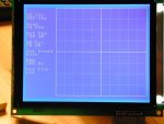
At the moment, to write the graticule requires 130 ms. The routine is crude and has CASE and IF...THEN branches in it to distinguish between solid lines and dotted line. These comparison operations and branches are usually time-killers, so they will be replaced later with separate in-line procedures to write solid lines and then one to write dotted lines.

I like the idea of display page flip. It would be a huge time saver if the display memory and controller would accommodate 4 layers. 1 text, 1 static graphic (the graticule) and two data layers for flipping. Whether this is possible is another question.

I'm familiar with Bressenham, as I started writing code before the days of micro computers. (IBM 360 in FORTRAN, to be exact.) However, in this particular case, sophisticated line drawing routines aren't necessary. That is because the display area is 240 pixels wide and I will have 240 data samples. In this case, lines connecting the data samples default to vertical lines. Thus in the crudest form, the line connection algorithm is:

To draw the line connecting points N and N+1 where the Y values corresponding to data points are held in array Y:

1. At column N, start the vertical line at Y[N] and stop it at Y[N+1]

2. Repeat until done.

There are no horizontal lines per se to draw, so the algorithm is much simpler.

The complicating fact is how the LCD memory is mapped, as a single pixel vertical line requires fussing with bits within each row's byte array. It would be much easier if the display could be rotated 90 degrees so the memory bytes were mapped vertically.

The RF part of the project, which includes a DDS synthesizer, mixer, selective crystal filters, log amp detector is already finished in breadboard.

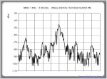
The attached image shows a spectrum analyzer data capture with 256 data points (256 sample points, each sample point has 8-bit resolution). The image is of an AM broadcast station, taken with an HP analog spectrum analyzer and a PIC-based A/D capture device that I built, and Windows software I wrote.
My current project is a smaller, highly customized version of a spectrum analyzer, so the data to be plotted will be quite similar.
 

CF Tech

Administrator
It looks like you are on the right track.

I think you will have to optimize the display access with assembly to hit your performance target.

You might consider doing a general purpose line routine instead of a special purpose, because:

1) a nicely optimized general purpose routine will not be much worse performance wise than the special purpose

2) you customers will want to be able to "zoom" in on the data

I think there is a monochrome VGA mode that has the pixels laid out in the same orientation as this display. The Abrash book should have an x86 assembly routine for that mode, and if so it should be fairly straight forward to port the routine to the PIC.

To each their own on languages, but I'm curious why C strikes you as so bad? Once I got over the cryptic syntax I never looked back to Pascal (which was my first love ;) ). A good C compiler gives almost effortless ability to drop into inline assembler which is great for projects like this: code it all in C, then just optimize the loops with inline ASM.

Of course . . . if you were going to switch to C, you would want to look at the AVR. This is a killer C machine (16 MIPS at 16MHz, vs. about 10 MIPS at 40MHz for the PIC IIRC, plus a really efficient architecture). Team it up with WinAVR plus AVR studio and all you have to pay for is the JTAG ICE for a really great development environment.
 

JackOfVA

New member
The particular application does not require zooming in the sense of a typical "5X or 10X" 'scope magnifier.

I have a long way to go before the software is finished and I'm sure that there will many dead ends and twists before it is completed.

As far as C goes, I've never found it particularly user friendly. All the PIC languages I've used, Pascal and BASIC, permit seamless drop-in assembler code.

In fact, dropping assembler into BASIC via a process of stepwise-refinement is the subject of a chapter in my book, "Programming the PIC Microcontroller with MBasic."
 

cmp241

New member
help with graticule

Hello again,

I am glad everything is working out. It seems like our projects are similar.

I too need to create a graticle. My project is basically an oscilloscope. when I draw a straight vertical or horizontal line, the lines are not continuous. it breaks up and at the gaps between the line the pixel shows up to the left or to the right of the gap.

attach is my code

the three main functions to control the line is
void horline( int32 x1, int32 x2, int32 y)
void vertline( int32 y1, int32 y2, int32 x)
void glcd_pixel(int16 x, int16 y, int1 color)

1. I believe it may be my addressing of the layers.
2. maybe the space between each pixel.

This is really depressing, not being able to draw a simple continous line. Please help me

Thanks,
Cedric
 

Attachments

JackOfVA

New member
Cedric:

I'll look the code over during the next few days--at least to my limited ability to read C programs.

Do you have a photo of the screen showing the break?

I've had similar breaks in my lines when developing code, and it's usually been a problem with an error in computing or setting the cursor address.

Drawing continuous horizontal lines is easier than vertical lines.

Jack
 
Top