The clock rate is 40 MHz, which is the maximum for the 18F458. That particular PIC is getting close to obsolete, so the final project may use an 18F4580, which is an updated version.
The limiting factor is not memory, but rather I/O writes to the LCD. To write a byte to the LCD currently runs about 40 us. That's total overhead, including the FOR loop, procedure calls to WriteByte routines and the like. There's lots of room for improvement there.
The programming language is Mikro Pascal 3.2. It is reasonably fast, but I know that some of the routines will have to be written in assembler, but my plan is to get it running in Pascal and then selectively port over to assembler the procedures that are time sensitive. I have a personal dislike for "C" and its derivatives, with Pascal being my preference for a programming language wherever possible.
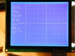
At the moment, to write the graticule requires 130 ms. The routine is crude and has CASE and IF...THEN branches in it to distinguish between solid lines and dotted line. These comparison operations and branches are usually time-killers, so they will be replaced later with separate in-line procedures to write solid lines and then one to write dotted lines.
I like the idea of display page flip. It would be a huge time saver if the display memory and controller would accommodate 4 layers. 1 text, 1 static graphic (the graticule) and two data layers for flipping. Whether this is possible is another question.
I'm familiar with Bressenham, as I started writing code before the days of micro computers. (IBM 360 in FORTRAN, to be exact.) However, in this particular case, sophisticated line drawing routines aren't necessary. That is because the display area is 240 pixels wide and I will have 240 data samples. In this case, lines connecting the data samples default to vertical lines. Thus in the crudest form, the line connection algorithm is:
To draw the line connecting points N and N+1 where the Y values corresponding to data points are held in array Y:
1. At column N, start the vertical line at Y[N] and stop it at Y[N+1]
2. Repeat until done.
There are no horizontal lines per se to draw, so the algorithm is much simpler.
The complicating fact is how the LCD memory is mapped, as a single pixel vertical line requires fussing with bits within each row's byte array. It would be much easier if the display could be rotated 90 degrees so the memory bytes were mapped vertically.
The RF part of the project, which includes a DDS synthesizer, mixer, selective crystal filters, log amp detector is already finished in breadboard.
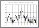
The attached image shows a spectrum analyzer data capture with 256 data points (256 sample points, each sample point has 8-bit resolution). The image is of an AM broadcast station, taken with an HP analog spectrum analyzer and a PIC-based A/D capture device that I built, and Windows software I wrote.
My current project is a smaller, highly customized version of a spectrum analyzer, so the data to be plotted will be quite similar.


