CFA-635 Logic-Level Serial

wintermute3

New member
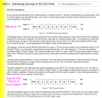
Bringing up new hardware which uses the subject display. Display lights up fine, and I have scoped the serial interface and voltage levels hitting the display input look good. We converted an existing, working USB-based system, so I know that we are sending valid packets and crc's. But the display will not respond. Can you confirm that we are using the right polarity and such? Sending 115200n8 with 5v == 1 and 0v == 0, idle mark level is 5v == 1, start bit is 0v == 0, 8 data bits sent LSB first, MSB last, stop bit 5v == 1, then back to idle mark 5v == 1. Data is positive true (1 bits are 5v, 0 bits are 0v).

Does all this sound correct? Thanks!

- Michael
Looking for additional LCD resources? Check out our LCD blog for the latest developments in LCD technology.
 

wintermute3

New member
CFA-635 Logic-Level Serial - Additional Info

Also, just to be complete, the only connections (4) to the module are +5V power, GND, and the serial in and out lines. Do we need to connect any of the other signals to utilize the module?

- Michael
 
idle mark level is 5v == 1, start bit is 0v == 0
That is inverted by RS232 standards. Normally idle is -V, and start bit is +V. So you will have to invert your signal, or find out from CFA whether you can change any jumper settings (the data sheet says you can only change JPF). Seems peculiar to me (restricting the jumper info), since the product description says "RS232 or 0-5V" interface.
 

wintermute3

New member
I wondered about that, but it is unclear from the datasheet. I wish they would publish the schematic of their RS-232 converter - that would make things unambiguous.

I assumed that the statement (elsewhere in these forums) that the logic-level serial interface was simply a connection to the embedded microcontroller's serial i/o pins meant that we were talking about positive logic levels without the confusing RS-232 inversion. In any case, I will see what I can do to try an inversion and see if there is any hope in that direction.

- Michael
 

CF Tech

Administrator
What do you mean by "We converted an existing, working USB-based system" ?

Did you send the module back to CF for new firmware?

The serial level board is just a "Max-232" style chip and connectors. Without it the microcontroller's logic level UART pins are brought out on H1, with the serial level board, the signal is inverted and stepped up to "real" RS-232 levels.

If you are talking to a "real" ES-232 device, you should use the serial converter board. If you are talking directly to a UART then you should connect signals on H1 directly.

All you need are +5v, GND, Rx and Tx
 

wintermute3

New member
The current design is 100% new hardware, designed for logic-level serial interface, with level converters for our 3.3V logic. I simply meant that I was confident that our software was producing a valid datastream, as that is the same as it was on the older USB-based hardware.

I am going to try to jury-rig an inversion in the serial path. It involves swapping the connections to two pins on a SOT-23-5 device, so it is me and the microscope once again...

- Michael
 

wintermute3

New member
So, is the inversion necessary? This is what I am currently sending:


...........start...............................stop
5.0v -----+...+---+---+---+---+---+---+---+---+---+---------
..........|...|...|...|...|...|...|...|...|...|
..........|...|...|...|...|...|...|...|...|...|
0.0v......+---+---+---+---+---+---+---+---+---+
...............d0..d1..d2..d3..d4..d5..d6..d7

Is this correct, or inverted?

- Michael
 
That is inverted, compared to real RS232. Like CF Tech says, you can remove the RS232 daughterboard, and connect directly to the H1 connector. The H1 pinouts are in the data sheet.
 

wintermute3

New member
There is no daughter-board. I am connecting directly to the H1 connector (this is a logic-level serial unit as purchased which never had a daughter-board). I know this is inverted relative to RS-232, what I am looking for is a straight-up confirmation that it is correct or that it is inverted for direct connection to the H1 connector. I am still unsure.

The statement that the serial i/o pins from the onboard uC are directly connected to the H1 connector would lead me to believe that my signal polarity is correct. After all, I am directly connecting the serial i/o pins from my onboard uC to the H1 connector to talk to the display unit. The only way it would seem to make sense that an inversion on my end is needed is if there is a TTL-level inversion on the logic lines on the H1 connector itself. Not having schematics for either the display unit or the RS-232 daughterboard leaves this ambiguous.

- Michael
 

wintermute3

New member
Thanks - that confirms that I am using the correct levels directly on the H1 connector. Which unfortunately leaves me still wondering why things are not working. :-(

So, if I have:

1) Correct polarity
2) Correct baud rate (115200, no parity, 1 stop)
3) Correct connections (+5V, GND, IN, OUT)
4) Good packet stream ( [0c,01,00,b7,7a] for instance)

And the unit still does not respond, what else could it be?

- Michael
 

wintermute3

New member
Problem Solved!

Ok - I finally found the issue. My level-shifters were not sufficiently agile for 115200 bps, and were distorting the 1/0 and 0/1 transition times. So, even though the overall timing of the serial data frames was correct, the individual bit times were off by about 20%, which was enough to corrupt the packet integrity.

Level inversion was not the issue - the logic-level interface uses non-inverted signals (contrary to the statement on page 6 of the user's guide:

> The CFA635-TMF-KL simply exposes these UART Tx & Rx (inverted,
> logic level, 0v to 5v nominal) signals on pin 1 and pin 2 of the CFA-635's
> expansion header H1.

Actually, I didn't even really need level shifters for the RX signal into the LCD unit, as it's inputs work just fine with a 3.3V logic signal.

- Michael
 

CF Tech

Administrator
> contrary to the statement on page 6 of the user's guide

The +10v / -10v "True RS232" levels are well defined.

The "logic level" signals are level shifted and inverted from those:

Space => +10v => 0v

Mark => -10v => +5v

So although the manual may not be as clear as it could be, I do not think it is an error.

> didn't even really need level shifters

Please be careful with that. You might be on the edge of the voltage range, which can set you up for hard to find errors when temperatures and voltages change. Make sure the maximum and minimums guarantee that a 1 is seen as a 1 and a 0 as a 0. Just working once on the bench is not enough.
 
Top