Jeff Gilbertson
Message 3 of 8 , Mar 9, 2006
View Source
I replaced mine in my QS8 a couple weeks ago, after more than two
years of playing it without a working LCD! Once I found some
instructions I thought I'd give it a shot. The instructions were okay
but not great (no part number, other things, see below) so I've been
meaning to type up some myself. I'd better do it now before I
completely forget what I did!
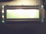
I'm assuming the QS6 has the same display. This is what I bought:
http://www.crystalfontz.com/products/1602c-wt/index.html#CFAH1602CYYHJP
Part number CFAH1602CYYHJP
$12 + $9 shipping = $21
This is a standard Hitachi 44780 compatible LCD display, but the
Alesis OEM part is not. What this means is you have to do a little
tricky wiring. The posts I've read over here
http://www.midiworld.com/quadrasynth/qs-forum/
all talk about swapping pins 3 and 4, 5 and 6, etc. up to 14 but I've
found what might be an easier way using the original QS connector
cable. Look at the back view picture on the crystalfontz picture and
you'll see the original cable could potentially fit. It does, but the
crystalfontz part does not come with a connector--you'll have solder
one on. What I did was buy a 16 pin IC wire wrap socket, break it in
half and thread it through the holes from the opposite side. After I
soldered the stakes in I ended up having to break off the black
plastic portion cause it interfered with mounting the LCD in the
keyboard (the dimensions are correct BTW, it fits in fine). A better
approach might be to get some Y stakes, thread them through the pin
holes and use the Alesis cable to keep them steady while you solder
them on. Or use the stakes from the connector on the old LCD.
If you do it this way, pins 4-14 end up matching correctly, and you
just have to fix the other ones. To do this, don't solder in stakes
for pins 1, 2, 3, 15, and 16 on the crystalfontz LCD. You'll need to
wire them differently as follows:
Pin 1 to 16
Pin 2 to 15
Pin 1, 2, and 3 to a potentiometer; I used a 10K. Pin 3 gets the
middle pin. Make sure you have access to the pot when the cable is
attached. I was able to make mine accessible without using any wires,
just the pot leads.
You'll also need two wire leads, one connected to pin 1 and one to pin
2. When you attach the QS connector to the LCD, pins 1 and 2 need to
be swapped, so that's why you can't use stakes. I just used tinned
wirewrap wire and it is sticking well (it hasn't fallen out yet).
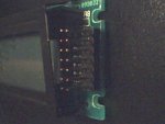
Make sure you plug in the cable the right way--the red wire goes
farthest away from the keys on the QS, and matches up with pin 1 and 2
on the LCD. The QS connector is only 14 pins so pins 15 and 16 on the
LCD won't be covered at all (but you wired them to pins 2 and 1 earlier).
Then you turn on the keyboard and adjust the pot until the display has
the right contrast.
Ahh.. maybe this isn't exactly easier but you don't have to destroy
your old cable or make a new one. And if you salvage the connector
from your old LCD the only extra stuff you need to buy is a pot and
some wire (and soldering equipment if you don't have any--in that case
you might want to have a friend do this for you!)


