633 ATX pwr

Quadphile

New member
the display's working fine, wiring is for sure correct. Short the Vsb to the pwr button output on the display and the mobo turns on.

I've mucked up the I/o mask in trying to get it to work properly, so i need to know what to send to get that working...moreover how to convert what the datasheet says to what i put in wintest.

what i tried (before mucking up the i/o pins) was:
send cmd 28 \212 for an inverted pwr button, and no reset, i need a pulse high.

send cmd 4 to save all settings

this board may need a pulse longer than 1sec, don't know for sure.

If you know off hand how to get MBM5 to be able to monitor the fans and temps is would be nice to know and save me some head bashing against the monitor...being in engineering I get grumpy when things don't work as my time is really tight.

Thanks again,
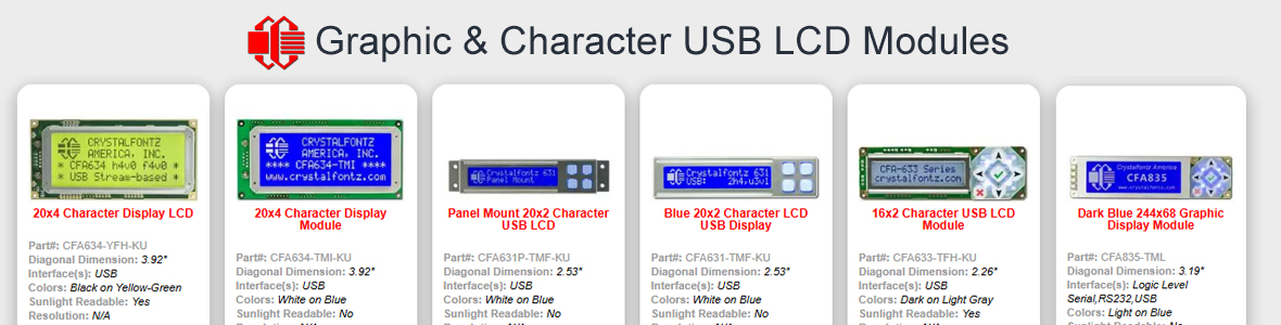
Looking for additional LCD resources? Check out our LCD blog for the latest developments in LCD technology.
 

jc634

Administrator
Quadphile said:


If you know off hand how to get MBM5 to be able to monitor the fans and temps is would be nice to know and save me some head bashing against the monitor...being in engineering I get grumpy when things don't work as my time is really tight.

Thanks again,
Search the CC2 User Screen forum. You should find the info you need there to get MBM up and running.

Jim
 

Quadphile

New member
Coming back today I realise I forgot to actually state what I needed help with ...but the second issue I now know where to look (that's an issue with being a newbie...where do you find what you need)

Anyway, I need to know exactly what I need to send to the display to get ATX pwr working. I've probably messed up the I/o status of the pins with cmd 34.

what do i send to:

1. fix the I/O to work properly, as I have no clue anymore after trying to get it to work what status they have anymore. I was reading the datasheet and had no success as yet doing my interpretation of the dataseet.

2. set up the atx pwr correctly to give me an inverted power button as i mentioned before (drive the output high)

3. save the settings (this should be cmd 4, with no data)

PS. how do i send cmd 28, so that i can change the pulse time (if it doesn't work then this is what the problem will be so if I know about how that works now it will be a great help) And can the pulse length be other than what is listed in the data sheet? (use 32 for one second???)
 

jc634

Administrator
Quadphile said:
Coming back today I realise I forgot to actually state what I needed help with ...but the second issue I now know where to look (that's an issue with being a newbie...where do you find what you need)

Anyway, I need to know exactly what I need to send to the display to get ATX pwr working. I've probably messed up the I/o status of the pins with cmd 34.

what do i send to:

1. fix the I/O to work properly, as I have no clue anymore after trying to get it to work what status they have anymore. I was reading the datasheet and had no success as yet doing my interpretation of the dataseet.

2. set up the atx pwr correctly to give me an inverted power button as i mentioned before (drive the output high)

3. save the settings (this should be cmd 4, with no data)

PS. how do i send cmd 28, so that i can change the pulse time (if it doesn't work then this is what the problem will be so if I know about how that works now it will be a great help) And can the pulse length be other than what is listed in the data sheet? (use 32 for one second???)
I don't have a 633, so I can't help you there. Hopefully, CF Tech may be able to help you on this. Also, you might post in the CC2 forum regarding ATX control and CC2. CC admin may be able to provide assistance regarding this combo.

Jim
 

CF Tech

Administrator
I think we have a command line script that will do this. We should probably post it here in the forum. Let me see what I can dig up when I get back to work.
 

CF Tech

Administrator
On my way home, I realized that this version was made before the GPIO, so it does not reset the GPIO. Here is a new script file that is updated for the v1.9 code.
 

Attachments

Quadphile

New member
I'm away from the computer that the display is on at the moment, but will try that script out. Looking at it you seem to combine each data chunk with a "\" so to send two chunks as the datasheet has you go "\100\115" etc.

Once its initialized, what should I be sending to it to invert the ATX control for power? (that'll save me some troubleshooting time). Using wintest of course.
 

CF Tech

Administrator
The script interpreter throws away ";;" comments, displays but otherwise ignores ";" comments, then builds a packet out of each remaining line.

Each byte is represented by a three-digit decimal value, prefixed by "\":

\000
\001
. . .
\255

Or just dumb-old ASCII characters.

The first one is the command, the second the length of the data, then there must be "length" bytes following, which will be interpreted as the data.

The script interpreter then sends the packet out the port, and waits for a response, printing copious debug information all along.
 
USB LCD Displays - Graphic and Character LCDs with a Keypad

Quadphile

New member
Still the same problem, the script seems to be hard-coded for a certain port, which i wasn't able to see right away from the code. The script can't see the display, it doesn't get any responses back and says error. Yet wintest works just fine.

q1. Which byte is sent first if entered in wintest, as well; which byte is which if you're reading the datasheet. Refer to page 36:

command = 34
length = 3
data[0] =2
data[1] =0
data[2] =2

for example. now with the information elsewhere in the datasheet I am either missing something or haven' been given enough information to work with here.

I sent command = 28 and typed in "\212\32" which should give me what i want, as well as a blank display while the computer is off. I then saved the current state after setting up the io with \001\000\003 \002\000\002 \003\000\002 all through the command 34. Neither of those two things happened, AND my computer's turning off every once in a while for no reason (may be power supply, just my luck) anyway if its the lcd, it is screwing up and driving the power_control line high (which is what i want) for a period of time long enough to do a hard power off...for no reason at all.

My understanding of how the packet debugger works is you select the command you want, then type the data and then send it. this means I should have been able to copy and paste the script defaults into wintest (minus the command type (such as the first number 34)) and have success. I did that and no go as of yet.

q2. am i interpreting the datasheet properly?

q3. please verify i'm trying to send the right stuff...i've got everything i've sent in the body of this message.
 

CF Tech

Administrator
The script's port can be changed.

Use WindowsKey + R, "cmd", enter to open a command prompt.

Then change directory to where you unzipped the file to, and run the program with the port and file as arguments:
 

Attachments

Quadphile

New member
Alright, the display is now initialized. What I did is there is a shortcut in the root of the folder in the scripter. I right clicked, and in the properties I changed the number in there corresponding to the correct port. I changed it to "2" since my LCD's on Com3, and the call to the program uses a ([Port#]-1) input parameter. I state this for anyone who has the same problem and stumbles upon this thread.

Now that everything is back to normal, and I can pretty much fool with anything I want, I will try once more with my interpretation of the user manual.

In the meantime, it wuld be nice to get a response as to what I need to type into wintest to get ATX functionality. I understand how the program works, just don't quite know for sure I'm sending the right thing

so let me know the command #, what it's called in the dropdown menu in wintest and then the exact text that should go in the data field, so like this:

cmd 28, set atx functionality "\212\32"
 

CF Tech

Administrator
The ATX can be confusing and cryptic
.

Look at "ATX POWER SUPPLY CONTROL CONNECTIONS" on page 8 of the CFA-633 data sheet:
Crystalfontz has a cable available (WRPWRY14) that simplifies ATX power control connections. When using this cable, please open jumper JP8 and close jumper JP9 in order to ensure correct operation. See “? JUMPER REFERENCE” for jumper positions.
and also "28: Set ATX Power Switch Functionality" on page 35.

In the simplest system, (negative active reset & power) you just need:
Code:
Command 28: \240
Couple of notes:

1) the \xxx syntax requires all three bytes. \032 is valid \32 is not.

2) The scripter needs the command and the length as the first two items on a line. The WinTest programs provide you with a pull-down for the length, and automatically calculate the length.
 

Quadphile

New member
Finally!!!!

Alright, for CF Tech, it's working fine, no need to reply (leaving me able to feild questions). For all those who may stumble upon this thread, let me let you in on what had me stumped.

1. the display resets when you turn the power on, so you must save whatever you do as the boot state, this will include the fans...no more vacuum cleaner until you get to the OS!!! In order to save the boot state, use command 4, and no data in the data field.

2. In order to get the ATX power to work, assuming you've got the connections correct, you must send it, usng command 28 the options to use. Data[0] is typed into wintest first, preceeded by enough zeros to give a total of three characters. Followed by data[1] and data[2]. all separated by a "\".

So in my case, where I need an inverted power line, LCD_off_is_host_off, Keypad_power_on and keypadpower_off, if you add all the options together that you want, in HEXADECIMAL of course, and then convert that number to decimal, you have data[0] to send. The information you need to refer to is on page 37 of the datasheet, and part#1 uses information from pages 35 and 36.

Here's what you do:
1. using command 34, send (three separate sends):
\001\000\003
\002\000\002
\003\000\002
2. using command 28 and the value calculated earlier, and a multiple of 1/32nd of a second that you requre for the length of the pulse, you send:
\212\032

in my case the options work out to 212, and i wanted a 1 second pulse, so that's what you enter. (32/32 = 1)

If there's something else you need to do, you now know enough to go through the datasheet and change any feature you want. OR reverse engineer how I did this to understand the datasheet.

If no one responds, I can feild questions on this matter, as I'm sure CF Tech has his/her hands full, and now that I understand how it works, it should be pretty simple to help out...as you can see I've had trouble for a couple weeks, and had there been a post such as this one I'dve had it going in a day's time.

Finally, remember that if you muck settings up (to a certain extent...don't know if its possible to render the display garbage through software) you can use the 633 script to reset the display. This will erase the default display and put Fwx.x and hw x.x. Oh no you think, now i have no idea what version of display I have. To solve this, send cmd 1, take the display's response reading, and type that into the main window of wintest. where the x's are. now click the send button beside the field you changed (the display now should be changed), and go to the packet debugger, send command 4 and no data, and you're back to where you started.
 
Top