
Hello,
I'm back with a new LCD. I have used this type of interface before and have a few different LCDs working on different projects. Here's a new issue.
I have an LEDBL-51852, which is based on the F-51852. It uses a NJU6676 controller, a very similar setup to the post below entitled "Optrex F-51553 Display Problems".
I am using the serial interface, and that seems to be operational, even though reading the display is disabled when using serial communications. I can tell it is working because when I measure the voltage at Vout, it jumps to -9.9 volts when I send the command to activate the power circuits. Also, when I send the contrast command to change to voltage at V5, I can see the voltage changing, from about -9.5 volts to -9.9 volts.
The problem is that I never see a change on the display. Even though I see the voltage changing on V5, the contrast on the screen doesn't change. Also, I an trying to write different values to the screen memory, but I see nothing on the screen. It looks like all pixels are off, but they might be all on. I've tried sending different setup commands like reversing the common output signals and display polarity.
Here are the voltages I'm reading:
Vout -9.9
V5 -9.9
V4 -8.0
V3 -6.4
V2 +1.8
V1 +2.4
VDD +5.0
One interesting thing is that when the V5 voltage changes, Vout changes also, and reads the same voltage as V5.
Here is the setup code I'm using:
Then I fill the data memory with half ones and half zeros..
Then I loop changing the contrast ratio.
So, I never see any change on the screen. Any ideas please?
Thanks,
Jeff
I'm back with a new LCD. I have used this type of interface before and have a few different LCDs working on different projects. Here's a new issue.
I have an LEDBL-51852, which is based on the F-51852. It uses a NJU6676 controller, a very similar setup to the post below entitled "Optrex F-51553 Display Problems".
I am using the serial interface, and that seems to be operational, even though reading the display is disabled when using serial communications. I can tell it is working because when I measure the voltage at Vout, it jumps to -9.9 volts when I send the command to activate the power circuits. Also, when I send the contrast command to change to voltage at V5, I can see the voltage changing, from about -9.5 volts to -9.9 volts.
The problem is that I never see a change on the display. Even though I see the voltage changing on V5, the contrast on the screen doesn't change. Also, I an trying to write different values to the screen memory, but I see nothing on the screen. It looks like all pixels are off, but they might be all on. I've tried sending different setup commands like reversing the common output signals and display polarity.
Here are the voltages I'm reading:
Vout -9.9
V5 -9.9
V4 -8.0
V3 -6.4
V2 +1.8
V1 +2.4
VDD +5.0
One interesting thing is that when the V5 voltage changes, Vout changes also, and reads the same voltage as V5.
Here is the setup code I'm using:
Code:
	DISP_RS = 0;	// hard reset
	delayMS( 2 );
	DISP_RS = 1;
	delayMS( 1 );

	LcdCmd( AdcSelectReverse );	// A1
	LcdCmd( CommonOutputNormal );	// C0
	LcdCmd( LcdBias1_9 );			// A2
	LcdCmd( DisplayNormal );		// A6

//	LcdCmd( V5ResistorRatio );		// 26  -- not available on this controller

	LcdCmd( ElectronicVolumeSet );	// 81 -- set evr mode
	LcdCmd( 	0x38 );				// set voltage at pin V5 (contrast)

	LcdCmd( 0xAC );			// static indicator off
	LcdCmd( 0 );

	// i ususally follow this power-up procedure, but this controller says
        // the first two steps are not necessary. No change either way...
//	LcdCmd( PowerControlSet | BoosterCircuit );
//	delayMS(10);
//	LcdCmd( PowerControlSet | BoosterCircuit | VoltageRegulator );
//	delayMS(10);
	LcdCmd( PowerControlSet | BoosterCircuit | VoltageRegulator | VoltageFollower );
	delayMS(10);
Then I fill the data memory with half ones and half zeros..
Code:
	LcdCmd( StartLineSet );                               // 0x40
	for( page=0; page < 8; page++ ) {

		LcdCmd( PageAddressSet + (page) );		// 0xB0

		LcdCmd( ColumnAddressHigh + 0 );		// 0x10	column 0
		LcdCmd( ColumnAddressLow + 0 );		// 0x00	column 0

		for( i=0; i<128; i++ ) {
			LcdData( 0xF0 );		// fill screen with checkers
		}
	}
	LcdCmd( DisplayOn );
Then I loop changing the contrast ratio.
Code:
	temp = 0;
	while(1) {

		LcdCmd( ElectronicVolumeSet );	// 81 -- set evr mode
		LcdCmd( temp );			// set voltage at pin V5 (contrast)

		delayMS(40);

		if( ++temp > 0x3F ) {
			temp = 0;
		}
	}
So, I never see any change on the screen. Any ideas please?
Thanks,
Jeff
Looking for additional LCD resources? Check out our LCD blog for the latest developments in LCD technology.
Attachments
-
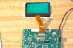 F-51852 LCD.JPG230.1 KB · Views: 961

