Review and Comment my schematics using CFAL4864A-071BW

enojeon

New member


Hi All,

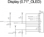
I attached a file that is schematics using CFAL4864A-071BW

I'd like to use '1.8V' logic level.
So, I connect to Vdd 1.8V.
Is it possible?


Refer Nets of that schematics.


+3.2V : 3.2V / 100mA

VDD_S : 1.8V / 200mA

SDA_2 : I2C Data

SCL_2 : I2C Clock

/OLED_RST : Connect to GPIO of MCU


Refer parts of that schematics.

CON2 : connector for CFAL4864A-071BW


That is for Wearable Device.


Review & Comment my schematics , ASAP.


Best Regards,

Inho Jeon.
Looking for additional LCD resources? Check out our LCD blog for the latest developments in LCD technology.
 

Attachments

CF Tech

Administrator
The module is rated only for 3.3v.

There are voltage multiplying parts on the tail that reduce the number of pins needed. These are chosen to work for the 3.3v.

I have not experimented with using a lower logic voltage. You could study the controller datasheet and see if it might work give the components we have chosen for the tail.

I'm not saying that your idea of using lower logic voltage can't work, but you would be on your own with the controller datasheet for that one.
 

enojeon

New member
Review and Comment my schematics using CFAL4864A-071BW (4-wire SPI Interface)


H
i All,

I attached a file that is schematics using CFAL4864A-071BW(4-wrie SPI Interface)


Refer Nets of that schematics.


+3.2V : 3.2V / 100mA

/OLED_RST' : Connect to GPIO port of MCU

OLED_SPI_MOSI' :
Connect to SPI MOSI port of MCU
OLED_SPI_CLK' : Connect to SPI CLK port of MCU

OLED_DC' : Connect to GPIO port of MCU

OLED_SPI_CS' : Connect to SPI CS port of MCU


Refer parts of that schematics.
CON2 : connector for CFAL4864A-071BW


That is for Wearable Device.

Review & Comment my schematics , ASAP.


Best Regards,

Inho Jeon.
 

Attachments

CF Tech

Administrator
Jeon:

I think it looks pretty good.

It will not hurt, but you probably do not need the pull up on /CS. One option would be to use your microcontroller's pull-up. Another option is to just drive /CS high as soon as your micro boots, then control /CS as normal, idling it high when you are not talking to the display.

Your reset circuit will work . . . most of the time.

There is a situation when the power is removed for a very short period (glitch). The processor will reset, but the capacitor C41 will not have time to discharge, so the display will not reset. If you have a free GPIO port on your micro, just manually drive /OLED_RST with that port. Then you do not need R10 or C41. This solution is very clean and gives you complete control in the firmware.

If you do not have a free GPIO, the reset on some microcontrollers will drive low as they detect power glitches, perhaps that could be used to reset the OLED.

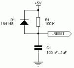
The RC reset like you have can be "fixed" with a diode, but that is another component, why add that if you have a GPIO you can use?
 

Attachments

enojeon

New member
Dear CF Tech,
Thank you for your reply.

I have 3 question below this;

1.
You mean,
If it possible contol in F/W of my MCU ports connected 'CS#' & '/RES#' of 'CFAL4864A-071BW ', do not need parts(R10,R2,C41)
,Is that right?

2.
You said, C41 is not properly, recomment value of C41, please.

3.
Unfortunately I have not add GPIO ports.

Best Regards,
Inho Jeon.
 

CF Tech

Administrator
1. You mean, If it possible contol in F/W of my MCU ports connected 'CS#' & '/RES#' of 'CFAL4864A-071BW ', do not need parts(R10,R2,C41), Is that right?
. . .
3. Unfortunately I have not add GPIO ports.
Yes, if you have free GPIO, you do not need those components. If you do not have the GPIO then you can use the components.

2. You said, C41 is not properly, recomment value of C41, please.
Typically you want a resistor, capacitor and diode to make a reasonably robust reset circuit:


ref: https://forum.arduino.cc/index.php?topic=331981.0
 

Attachments

Top