Yet another CFAG320240CX-TFHTTS to HC12 intialization problem

reg417

New member
Yet another CFAG320240CX-TFHTTS to HCS12 intialization problem

I have searched extensively through the forum for similar problems but cannot clearly detect my own problem still!

I've attempted initialization on the LCD screen in a handful of different ways, including following the indirect addressing initialization instructions as outlined on page 103 in Appendix C, following the C++ example as outlined in Appendix B, and following the example in the downloadable WinTest with no success.

Would someone please take a look through my code? I have checked my connections over and over and verified them.

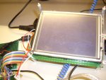
On my 9S12, I am using PORT T to send commands and PORT A/D (as general purpose I/O) to send data to the LCD.

PORT T:
Bit 0: E
Bit 1: /CS
Bit 2: A0
Bit 3: /RES
and I have R/W hardwired low, and DISPOFF as N/C.

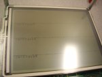
Everytime I load it up on my LCD, all I get are tiny bent lines on the top and bottom edges of the screen, randomly each time in different places along the edges. I can't write even one word, yet I am looking to write out a bitmap hopefully soon! :(

Code:
//============================================================================
// Macros

#define CLEAR_E     PORTT|=0x01
#define SET_E       PORTT&=~0x01
#define CLEAR_CS    PORTT|=0x02
#define SET_CS      PORTT&=~0x02
#define SET_A0      PORTT|=0x04
#define CLEAR_A0    PORTT&=~0x04
#define CLEAR_RES   PORTT|=0x08
#define SET_RES     PORTT&=~0x08

//============================================================================
// Commonly used commands

#define Uchar unsigned char
#define Uint unsigned int

#define SYSTEM_SET    0x40

Uchar SystemSetArray[] = {
    0x38, 0x87, 0x07, 0x3F, 0x49, 0x7F, 0x80, 0x00
};

#define SCROLL      0x44

#define SAD1   0x00
#define SAD2   0x10
#define SAD3   0x04
#define SAD4   0x30

Uchar ScrollArray[] = {
    0x00, SAD1, 0x40, 0x00, SAD2, 0x40, 0x00, SAD3, 0x00, SAD4
};

#define HDOT_SCR    0x5A
#define OVLAY        0x5B

#define DISP_OFF    0x58
#define DISP_ON        0x59

#define CSRW        0x46
#define CSR_FORM    0x5D
#define CSR_DIR_R    0x4C
#define CSR_DIR_L    0x4D
#define CSR_DIR_U    0x4E
#define CSR_DIR_D    0x4F

#define MWRITE        0x42
#define MREAD        0x43

#define BUSY        0x40    // 0b0100 0000
#define PARA_P9        0x28    // 320 x 240
#define SLEEP_IN 0x53

//============================================================================
// Function prototypes

void delay(Uint);
void writeCommand(Uchar);
void writeData(Uchar);
void clearLayer1(void);
void clearLayer2(void);
void lcdInit(void);

//============================================================================
// Main

int main(void)
{
    Uint i;

    DDRAD = 0xFF;    // Configure Port AD as output
    DDRT = 0xFF;    // Configure Port T as output

    PTAD = 0x00;
    PORTT = 0x00;

    delay(6000);    // Time for LCD to get ready

    // Initialize LCD
    lcdInit();

    // Write to LCD; display something
    writeCommand(MWRITE);
    writeData(0x20);    // Character: space
    writeData(0x4A);    // Character: J
    writeData(0x65);    // Character: e
    writeData(0x72);    // Character: r
    writeData(0x6B);    // Character: k
    writeData(0x66);    // Character: f
    writeData(0x61);    // Character: a
    writeData(0x63);    // Character: c
    writeData(0x65);    // Character: e

    writeCommand(CSRW);
    writeData(0x00);    // Set cursor to start of second screen block
    writeData(0x10);
    writeCommand(CSR_DIR_D);    // Set cursor shift direction to down

    writeCommand(MWRITE);
    for (i = 0; i < 9; i++)
        writeData(0xFF);    // Fill in a square to the left of the 'J'

    return 0;
}

//============================================================================
// Functional specification

// Time delay in ticks
void delay(Uint ticks)
{
    while(ticks != 0)
        ticks--;
}

// COM_W
void writeCommand(Uchar CommandByte)
{
    PTAD = CommandByte;
    SET_A0;
    CLEAR_CS;
    //R/W is hardwired low
    SET_E;
    CLEAR_E;
    SET_CS;
}

// DATA_W
void writeData(Uchar dataW)
{
    PTAD = dataW;
    CLEAR_A0;
    CLEAR_CS;
    //R/W is hardwired low
    SET_E;
    CLEAR_E;
    SET_CS;
}

void clearLayer1(void)
{
    Uint i;
    Uchar c;
    c = 'A';

    // CALL POS1
    writeCommand(CSRW);
    writeData(0x00);
    writeData(0x00);
    // Clear loop
    writeCommand(MWRITE);
    CLEAR_A0;
    CLEAR_CS;

    for (i = 0; i < ((0x28) * 30); i++)  // 30 * APL
    {
        PTAD = ' ';
        if ('Z' < c)
            c = 'A';
        SET_E;
        CLEAR_E;
    }
    SET_CS;
}

void clearLayer2(void)
{
    Uint i;

    // CALL POS2
    writeCommand(CSRW);
    writeData(0x60);
    writeData(0x09);
    // Clear loop
    writeCommand(MWRITE);
    CLEAR_A0;
    CLEAR_CS;

    for (i = 0; i < ((0x28) * 240); i++)    // 240 * APL
    {
        PTAD = 0x00;
        SET_E;
        CLEAR_E;
    }
    SET_CS;
}

// Initialization
void lcdInit(void)
{
    Uchar i;

    // Idle the control lines & reset the display
    CLEAR_RES;
    CLEAR_E;
    CLEAR_A0;
    SET_CS;
    PTAD = 0x00;
    SET_RES;

    writeCommand(SYSTEM_SET);

    for (i = 0; i < 8; i++)
    {
        writeData(SystemSetArray[i]);
    }

    writeCommand(SCROLL);    // Initialize screen block start addresses

    for (i = 0; i < 10; i++)
    {
        writeData(ScrollArray[i]);
    }

    writeCommand(HDOT_SCR);
    writeData(0x00);    // Set horizontal pixel shift to zero
    writeCommand(OVLAY);
    writeData(0x01);    // First & third screen blocks are text mode

    writeCommand(DISP_OFF);
    writeData(0x56);    // Flash cursor at 2 Hz, and turn all screen blocks ON

    clearLayer1();  // Fill first screen layer with space characters
    clearLayer2();  // Fill second screen layer memory with blank data

    writeCommand(CSRW);
    writeData(0x00);    // Set cursor to start of first screen block
    writeData(0x00);

    writeCommand(CSR_FORM);
    writeData(0x04);    // Horizontal cursor size = 5 pixels
    writeData(0x86);    // Vertical cursor size = 7 pixels

    writeCommand(DISP_ON);

    writeCommand(CSR_DIR_R);    // Set cursor direction to right
}
Any help is greatly appreciated. Thanks in advance!
Looking for additional LCD resources? Check out our LCD blog for the latest developments in LCD technology.
 
Last edited:
It looks like you're operating the display in 6800 mode, and I'll assume the J68 jumper is in place.

Analyzing your control signal macros, it seems that you've got some of your control states inverted. I assume the macros are intended to make the signals easier to understand, where "CLEAR" would mean "inactive" (without regard to whether that state was a 1 or a 0), and "SET" would mean "active" (same). So I'll comment some of your macro defines, indicating whether the implied state is (correct) or (wrong):
Code:
#define CLEAR_E     PORTT|=0x01  // E goes high, which is the 'active' state (wrong)
#define SET_E       PORTT&=~0x01  // E goes low, inactive (wrong)
#define CLEAR_CS    PORTT|=0x02  // CS goes high, inactive (correct)
#define SET_CS      PORTT&=~0x02  // CS goes low, active (correct)
#define SET_A0      PORTT|=0x04
#define CLEAR_A0    PORTT&=~0x04
#define CLEAR_RES   PORTT|=0x08  // RES goes high, inactive (correct)
#define SET_RES     PORTT&=~0x08  // RES goes low, active (correct)
Now I'll put similar comments into some of your other functions:
Code:
void writeCommand(Uchar CommandByte)
{
    PTAD = CommandByte;
    SET_A0;
    CLEAR_CS;   // CS goes inactive (wrong)
    //R/W is hardwired low
    SET_E;   // E goes inactive (wrong)
    CLEAR_E;   // E goes active (wrong)
    SET_CS;   // CS goes active (wrong)
}

void writeData(Uchar dataW)
{
    PTAD = dataW;
    CLEAR_A0;
    CLEAR_CS;   // CS goes inactive (wrong)
    //R/W is hardwired low
    SET_E;   // E goes inactive (wrong)
    CLEAR_E;   // E goes active (wrong)
    SET_CS;   // CS goes active (wrong)
}

void lcdInit(void)
{
    Uchar i;

    // Idle the control lines & reset the display
    CLEAR_RES;   //RES goes inactive (wrong)
    CLEAR_E;    // E goes active (wrong)
    CLEAR_A0;
    SET_CS;   // CS goes active (wrong)
    PTAD = 0x00;
    SET_RES;   // RES goes active (wrong)
// snipped
So, it is no wonder nothing works. The display is held in reset. In the write functions the control states are inverted. I suggest that you change your control signal macros so that "CLEAR" = low and "SET" = high, or name them something else, like "ACTIVE" and "INACTIVE". Otherwise, there is too much confusion.

P.S. It occurs to me, after rereading this, that maybe your macros came from the WinTest source code, which are screwed up to account for the fact that some of the signals on a PC paralled port are inverted, and some aren't. Since you're using a straight logic hookup, those macros are inappropriate for you. In fact, its so confusing to me that maybe my analysis is wrong too :confused:.
 
Last edited:

reg417

New member
Ah, I see. Yes, the functions come from the WinTest code, and I had no idea about the PC's parallel port having some inverted pins. I will try to make changes and test the LCD this afternoon and tell you how it goes. Thanks very much for your reply!
 
Last edited:

reg417

New member
I changed the macro names to ACTIVE and INACTIVE as you suggested, which did feel a lot more comfortable to work with. Made some small changes with the wrong states in my previous code, but still I am not getting anything. Are my functions doing the wrong instructions as well?

Here is the revised code.
Code:
//============================================================================
// Macros

#define ACTIVE_E	PORTT|=0x01  // E goes high, which is the 'active' state
#define INACTIVE_E	PORTT&=~0x01  // E goes low, inactive
#define INACTIVE_CS	PORTT|=0x02  // CS goes high, inactive
#define ACTIVE_CS	PORTT&=~0x02  // CS goes low, active
#define ACTIVE_A0   PORTT|=0x04
#define INACTIVE_A0 PORTT&=~0x04
#define INACTIVE_RES	PORTT|=0x08  // RES goes high, inactive
#define ACTIVE_RES	PORTT&=~0x08  // RES goes low, active

//============================================================================
// Commonly used commands

#define Uchar unsigned char
#define Uint unsigned int

#define SYSTEM_SET    0x40

Uchar SystemSetArray[] = {
    0x38, 0x87, 0x07, 0x3F, 0x49, 0x7F, 0x80, 0x00
};

#define SCROLL      0x44

#define SAD1   0x00
#define SAD2   0x10
#define SAD3   0x04
#define SAD4   0x30

Uchar ScrollArray[] = {
    0x00, SAD1, 0x40, 0x00, SAD2, 0x40, 0x00, SAD3, 0x00, SAD4
};

#define HDOT_SCR    0x5A
#define OVLAY        0x5B

#define DISP_OFF    0x58
#define DISP_ON        0x59

#define CSRW        0x46
#define CSR_FORM    0x5D
#define CSR_DIR_R    0x4C
#define CSR_DIR_L    0x4D
#define CSR_DIR_U    0x4E
#define CSR_DIR_D    0x4F

#define MWRITE        0x42
#define MREAD        0x43

#define BUSY        0x40    // 0b0100 0000
#define PARA_P9        0x28    // 320 x 240
#define SLEEP_IN 0x53

//============================================================================
// Function prototypes

void delay(Uint);
void writeCommand(Uchar);
void writeData(Uchar);
void clearLayer1(void);
void clearLayer2(void);
void lcdInit(void);

//============================================================================
// Main

int main(void)
{
    Uint i;

	DDRT = 0xFF;    // Configure Port T as command output
    DDRAD = 0xFF;    // Configure Port AD as data output

    PORTT = 0x00;
    PTAD = 0x00;

    delay(600);    // Time for LCD to get ready

    // Initialize LCD
    lcdInit();

    // Write to LCD; display something
    writeCommand(MWRITE);
    writeData(0x20);    // Character: space
    writeData(0x4A);    // Character: J
    writeData(0x65);    // Character: e
    writeData(0x72);    // Character: r
    writeData(0x6B);    // Character: k
    writeData(0x66);    // Character: f
    writeData(0x61);    // Character: a
    writeData(0x63);    // Character: c
    writeData(0x65);    // Character: e

    writeCommand(CSRW);
    writeData(0x00);    // Set cursor to start of second screen block
    writeData(0x10);
    writeCommand(CSR_DIR_D);    // Set cursor shift direction to down

    return 0;
}

//============================================================================
// Functional specification

// Time delay in ticks
void delay(Uint ticks)
{
    while(ticks != 0)
        ticks--;
}

// COM_W
void writeCommand(Uchar CommandByte)
{
    PTAD = CommandByte;
    ACTIVE_A0;
    ACTIVE_CS;   // CS goes active
    //R/W is hardwired low
    ACTIVE_E;   // E goes active
    INACTIVE_E;   // E goes inactive
    INACTIVE_CS;   // CS goes inactive
    delay(300);
}

// DATA_W
void writeData(Uchar dataW)
{
    PTAD = dataW;
    INACTIVE_A0;
    ACTIVE_CS;   // CS goes active
    //R/W is hardwired low
    ACTIVE_E;   // E goes active
    INACTIVE_E;   // E goes inactive
    INACTIVE_CS;   // CS goes inactive
    delay(300);
}

void clearLayer1(void)
{
    Uint i;
    Uchar c;
    c = 'A';

    // CALL POS1
    writeCommand(CSRW);
    writeData(0x00);
    writeData(0x00);
    // Clear loop
    writeCommand(MWRITE);
    INACTIVE_A0;
    INACTIVE_CS;

    for (i = 0; i < ((0x28) * 30); i++)  // 30 * APL
    {
        PORTT = ' ';
        if ('Z' < c)
            c = 'A';
        ACTIVE_E;
        INACTIVE_E;
    }
    ACTIVE_CS;
}

void clearLayer2(void)
{
    Uint i;

    // CALL POS2
    writeCommand(CSRW);
    writeData(0x60);
    writeData(0x09);
    // Clear loop
    writeCommand(MWRITE);
    INACTIVE_A0;
    INACTIVE_CS;

    for (i = 0; i < ((0x28) * 240); i++)    // 240 * APL
    {
        PORTT = 0x00;
        ACTIVE_E;
        INACTIVE_E;
    }
    ACTIVE_CS;
}

// Initialization
void lcdInit(void)
{
    Uchar i;

    // Idle the control lines & reset the display
    ACTIVE_RES;   //RES goes active
    INACTIVE_E;    // E goes inactive
    INACTIVE_A0;
    INACTIVE_CS;   // CS goes inactive
    PTAD = 0x00;
    INACTIVE_RES;   // RES goes inactive

    writeCommand(SYSTEM_SET);

    for (i = 0; i < 8; i++)
    {
        writeData(SystemSetArray[i]);
    }

    writeCommand(SCROLL);    // Initialize screen block start addresses

    for (i = 0; i < 10; i++)
    {
        writeData(ScrollArray[i]);
    }

    writeCommand(HDOT_SCR);
    writeData(0x00);    // Set horizontal pixel shift to zero
    writeCommand(OVLAY);
    writeData(0x01);    // First & third screen blocks are text mode

    writeCommand(DISP_OFF);
    writeData(0x56);    // Flash cursor at 2 Hz, and turn all screen blocks ON

    clearLayer1();  // Fill first screen layer with space characters
    clearLayer2();  // Fill second screen layer memory with blank data

    writeCommand(CSRW);
    writeData(0x00);    // Set cursor to start of first screen block
    writeData(0x00);

    writeCommand(CSR_FORM);
    writeData(0x04);    // Horizontal cursor size = 5 pixels
    writeData(0x86);    // Vertical cursor size = 7 pixels

    writeCommand(DISP_ON);

    writeCommand(CSR_DIR_R);    // Set cursor direction to right
}
Other information about my connections:
Vss: GND (commonly connected to my micropocessor and power supply)
Vdd: +5.0 V
Vo: -21.3 V
FGND: N/C

I don't think I've burnt the LCD yet, since I already reverse-polaritied my last screen and was extra careful with this one. The current, when turned on, is between 67 and 75 mA, within the minimum and typical limits.
 
Vo seems a bit high, try turning it down to about -18v.

Your changes in the macros look OK, and the usage in the write functions looks OK (but see suggestion below). For the A0 macros, it would be easier to understand "#define DATA_A0 (blah blah)" and "#define CMD_A0 (blah blah)", don't you think so?

In your "clearLayer1" (& 2), your use of CS is backwards. You are disabling the display during your write loops. Here is a suggestion: throughout your entire code body, leave CS active (low state). There is no real need to keep changing it unless there is more than one device on the data bus.

Have you paid any attention to timing? From what I can see in the data sheet, the epson controller clock speed is 10 MHz, and the minimum E pulse width is 5 clock periods, so E should be greater than 500 nS wide. You have no delays in your code, so I suspect that your pulses are too short. What's the clock speed of the HCS12? Here's a suggestion for your write functions:
Code:
void writeCommand(Uchar CommandByte)
{
    // CS always active
    //R/W is hardwired low

    PTAD = CommandByte;
    ACTIVE_A0;
    ACTIVE_E;   // E goes active
    delay(US3);   // delay 3 microsec
    INACTIVE_E;   // E goes inactive
    delay(US3);   // delay 3 microsec
}

void writeData(Uchar dataW)
{
    PTAD = dataW;
    INACTIVE_A0;
    ACTIVE_E;   // E goes active
    delay(US3);   // delay 3 microsec
    INACTIVE_E;   // E goes inactive
    delay(US3);   // delay 3 microsec
}
Typically, I dislike using fixed delays, and would rather test for a "busy" flag, to maximize efficiency. However, I am unable to see any way to test for "busy" with this display, so delays are needed with fast host cpus. The reason there are no obvious delays in the WinTest code, is that they are in the SET_E macro (a whole slug of "Sleep(0);" statements).

BTW, I don't have this display, and have never used it, so I cannot tell if your init sequences are any good. If you copied them from the data sheet, they ought to work.

Afterthought: try tying DISPOFF (pin 19) high.
 
Last edited:

reg417

New member
I agree with the macros for A0--thanks for the suggestion. As for the Chip Select, I will later be using two LCDs on the same bus so I will figure that out later, but for now to initialize one screen I will keep it active throughout. Another good suggestion to simplify things.

And it is true that I did not pay attention to timing--that is my big mistake. My clock speed is 24 MHz, which makes one cycle 41.67 nanoseconds....Far too fast. I will add some delays now.

Thank you much for your help; I really really appreciate it. You are always so helpful around the forum!

Updates to follow...
 

reg417

New member


After introducing many time delays, I did manage to get a block of pixels covering the screen. Is this a good sign? I still was not able to get the text I coded for, but perhaps this is a start?

I included a picture of the block.
 

Attachments

This could be because your Vo is too high. That's why I suggested turning it down, a week ago. Do you get any change in the contrast of the full screen block by reducing Vo?
 

reg417

New member
Yes, after adjusting Vo to about -18 V, I still got the ominous block of pixels... All other voltages and current seem fine also.
 
What you need to do is turn down Vo until the pixels start to fade away. Then you can tell if any pixels are turned on by the controller or all are just over-ridden by too much panel bias.
 

reg417

New member
Sorry for the week-long replies, but I've been so swamped with other parts of this project. I did manage to get the screen displaying some things--yay! Thank you so so much! :D


It has a bit of garbage lines along with the text I wanted it to display....and it repeats 4 times. Is this okay? How can I adjust this?
 

Attachments

CF Tech

Administrator
I would think there is an error in the initializations for the 4x repeat to be happening.

Maybe look back through the initialization parts in the wintest code now that you have it going.
 

reg417

New member
I was able to narrow it down to repeat only one extra time by playing around with the frame height and horizontal address range registers...but it stills shows two.

I did manage to get a bitmap to display! :)
 
Last edited:

bboldt

New member
Need similar Help with LCD

Hello,

Glad to see that you finnally got your LCD working, I too am having similar issues with this same LCD. What final timing did you use to get your LCD to display?

also how did you hookup the voltages? I see that you were hooking up a negative voltage as well as the logic voltage, did you have better luck not using the built in negative supply?


Thanks in advance, Brad
 

reg417

New member
Hi, bboldt:

The timing doesn't need to be very accurate (or so it seems), but just make sure you have long delays, and then you can always scale them back later. For pulsing the Enable, I used a delay of approximately 3 microseconds in between raising it and lowering it and afterwards also. When enabling/disabling the Reset line, I gave a delay of 1 millisecond after each.

For the voltage hookup, I gave the +5 V for the logic voltage, and indeed used the built-in negative supply. Basically, I did not connect anything to V0, and just read its value while adjusting the contrast pot to vary it a little to about -18 or -19 initially, and then more/less for my graphic to display as I want.

If you are attempting to load a bitmap image, then don't follow the WinTest code strictly--I had to use a combination of the WinTest code with the code as presented in the example in Appendix B.

I still haven't gotten a single line of words to display (just multiple) but I gave up on that since my only goal is to display images anyway.
 

bboldt

New member
Thanks for your reply,

I read through this post and reworked my code to basically copy what has been done in this post. All I need for my class is to get something to happen on this LCD (any graphic or text or anything), I can worry about getting bitmaps and whatnot later, I just kind of want to see anything happen on this LCD

My setup is an Atmel ATMega324P, running at an 8MHz clock, with a 3.3V supply. The logic voltage on the LCD is also 3.3 (from the same supply). Problems i am having i believe are related to Voltages and contrast. The reason I say this is because The higest Vo value I get from using the internal negative voltage generator is -18.4. The specs I have state that the value of VLCD should = (Vdd - V0) = 23.8 with a value of 3.3 as Vdd and -18.4 as V0 (3.3-(-18.4)) = 21.7 which is 2 volts under spec.

Also my Vee value, (spec says it should be -25V) is only -18V when using the negative voltage generator. I tried using a lab supply to supply my own V0, but the best i could do is apply -22.2 volts and this would just be mimicked on the output at Vee. I dont know maybe that is supposed to do that, But even with a Vo value of -20.5, (whitch would give a value of (-3.3-(-20.5) = 23.8) according to the specs i have would be correct, i still cannot get anything to display on the LCD.


I attached my code that i wrote today below, like I said I tried to make it as similar as posisbly to the code listed in your forum because i just wanted to see if I could get anythign to display on the LCD.

Code:
/*****************************************************
This program was produced by the
CodeWizardAVR V1.25.7a Evaluation
Automatic Program Generator
© Copyright 1998-2007 Pavel Haiduc, HP InfoTech s.r.l.
[url]http://www.hpinfotech.com[/url]

Project : 
Version : 
Date    : 4/2/2008
Author  : Freeware, for evaluation and non-commercial use only
Company : 
Comments: 


Chip type           : ATmega324P
Program type        : Application
Clock frequency     : 8.000000 MHz
Memory model        : Small
External SRAM size  : 0
Data Stack size     : 512
*****************************************************/

#include <mega324.h>   
#include <delay.h>

#define SYSTEM_SET      0x40
#define DISPLAY_OFF     0x58
#define DISPLAY_ON     0x59
#define SCROLL          0x44
#define CSRFORM         0x5D
#define HDOT_SCR        0x5A
#define OVLAY           0x5B
#define CSRW            0x46
#define MWRITE          0x42
#define MREAD           0x43


#define CSDIR_RIGHT     0x4C
#define CSDIR_LEFT      0x4D
#define CSDIR_UP        0x4E
#define CSDIR_DOWN      0x4F 
#define GRAYSCLE        0x60  

#define LCD_DATA_OUT    PORTA
#define LCD_DATA_IN     PINA
#define LCD_CTRL        PORTC
#define LCD_DATA_DIR    DDRA 
#define LCD_CTRL_DIR    DDRC

#define OUTPUT          0xFF
#define INPUT           0x00

#define E       PORTC.3
#define RW      PORTC.4
#define A0      PORTC.5
#define RES     PORTC.6
#define CS      PORTC.7      


#define ACTIVE_E        E = 1;         //E goes high, the 'active' state
#define INACTIVE_E      E = 0;         //E goes low, the 'inactive' state

#define INACTIVE_CS     CS = 1;         //cs goes high, the 'inctive' state
#define ACTIVE_CS       CS = 0;         //CS goes low the 'active' state
                        
#define ACTIVE_A0       A0 = 1;         //A0 goes high, the 'active' state
#define INACTIVE_A0     A0 = 0;         //A0 goes low, the 'inactive' state

#define INACTIVE_RES    RES = 1;         //RES goes high, the 'inactive' state
#define ACTIVE_RES      RES = 0;         //RES goes low,  the 'active' state
    

#define LOW   0
#define HIGH  1


 // Declare your global variables here          
//============================================================================
// Function prototypes


void SD13700_send_command (char byte);
void SD13700_send_data (char byte);
void clearLayer1(void);
void clearLayer2(void);
void lcd_init(void); 

//==============================================================================
 

void main(void)
{
    
    DDRC = 0xFF;    // Configure Port C as command output
    DDRA = 0xFF;    // Configure Port A as data output

    PORTC = 0x00;
    PORTA = 0x00;
 while(1)
     { 
     RES = 1;           //RES goes inactive
    delay_ms(600);    // Time for LCD to get ready

    // Initialize LCD
    lcd_init;
RES = 1;           //RES goes inactive
    // Write to LCD; display something
    SD13700_send_command(MWRITE);
    SD13700_send_data(0x20);    // Character: space
    SD13700_send_data(0x4A);    // Character: J
    SD13700_send_data(0x65);    // Character: e
    SD13700_send_data(0x72);    // Character: r
    SD13700_send_data(0x6B);    // Character: k
    SD13700_send_data(0x66);    // Character: f
    SD13700_send_data(0x61);    // Character: a
    SD13700_send_data(0x63);    // Character: c
    SD13700_send_data(0x65);    // Character: e

    SD13700_send_command(CSRW);
    SD13700_send_data(0x00);    // Set cursor to start of second screen block
    SD13700_send_data(0x10);
    SD13700_send_command(CSDIR_DOWN);    // Set cursor shift direction to down
         }
//while (1);   //do nothing   
         }


void SD13700_send_command(char byte)
{

//cs is always active
//R/W is hardwired low

LCD_DATA_OUT = byte;
ACTIVE_A0;
ACTIVE_E;    //E goes active
delay_us(3);  // 3 microsecond delay 
INACTIVE_E;   //E goes inactive
delay_us(3);   //3 microsecond delay

}        
      
void SD13700_send_data(char byte)    
{
LCD_DATA_OUT = byte;
INACTIVE_A0;
ACTIVE_E;       //E goes active
delay_us(3);    //3 microsecond delay
INACTIVE_E;     //E goes inactive
delay_us(3);    //3 microsecond delay
 } 
 
         
         void clearLayer1(void)
{
    unsigned int i;
    unsigned char c;
    c = 'A';

    // CALL POS1  
    SD13700_send_command(CSRW);
    SD13700_send_data(0x00); 
    SD13700_send_data(0x00); 

    // Clear loop
    SD13700_send_command(MWRITE);
    INACTIVE_A0;
    //INACTIVE_CS;

    for (i = 0; i < ((0x28) * 30); i++)  // 30 * APL
    {
        LCD_DATA_OUT = ' ';
        if ('Z' < c)
            c = 'A';
        ACTIVE_E;
        INACTIVE_E;
    }
    //ACTIVE_CS;
}
         void clearLayer2(void)
{
    unsigned int i;

    // CALL POS2
    SD13700_send_command(CSRW);
     SD13700_send_data(0x60); 
    SD13700_send_data(0x09); 
    // Clear loop
    SD13700_send_command(MWRITE);
    INACTIVE_A0;
    //INACTIVE_CS;

    for (i = 0; i < ((0x28) * 240); i++)    // 240 * APL
    {
        LCD_DATA_OUT = 0x00;
        ACTIVE_E;
        INACTIVE_E;
    }
    //ACTIVE_CS;
}
       
 //initialization
  void lcd_init(void)
 {

        RES = 0;             //RES goes active
        INACTIVE_E;             //E goes inactive
        INACTIVE_A0;            
        ACTIVE_CS;            //CS goes active
        LCD_DATA_OUT = 0x00;
        RES = 1;           //RES goes inactive
        
        
        SD13700_send_command(SYSTEM_SET);                   //0x40
        SD13700_send_data(0x38);                            //P1  M0
        SD13700_send_data(0x87);                            //P2  FX
        SD13700_send_data(0x07);                            //P3  FY
        SD13700_send_data(0x3F);                            //P4  C/R 39 in decimal = 0x27h 
        SD13700_send_data(0x49);                            //P5  TC/R 41 in decimal = 0x29h   
        SD13700_send_data(0x7F);                            //P6  L/F 239 in decimal = 0xEFh
        SD13700_send_data(0x80);                            //P7  APL
        SD13700_send_data(0x00);                            //P8  APH


        SD13700_send_command(SCROLL);                      //0x44
        SD13700_send_data(0x00);                            //SAD 1L
        SD13700_send_data(0x00);                            //SAD 1H
        SD13700_send_data(0x40);                            //SL1  
        SD13700_send_data(0x00);                            //SAD 2L   
        SD13700_send_data(0x10);                            //SAD 2H   
        SD13700_send_data(0x40);                            //SL2   
        SD13700_send_data(0x00);                 
        SD13700_send_data(0x04);                            //SAD 2L   
        SD13700_send_data(0x00);                            //SAD 2H   
        SD13700_send_data(0x30); 
        
        SD13700_send_command(HDOT_SCR); //0x5A
        SD13700_send_data(0x00);            //no scroll
        
        SD13700_send_command(OVLAY);    //0x5B
        SD13700_send_data(0x01);          
        
        SD13700_send_command(DISPLAY_OFF);   
        SD13700_send_data(0x56);                //flash cursor at 2Hz, and turn all screen blocks on
        
        clearLayer1();
        clearLayer2();
        
        
       SD13700_send_command(CSRW);                 //0x46   
       SD13700_send_data(0x00);
       SD13700_send_data(0x00);
        
        SD13700_send_command(CSRFORM);
        SD13700_send_data(0x04);        //Horizontal cursor size = 5 pixels                               
        SD13700_send_data(0x86);        //Vertical cursor size = 7 pixels
                               
        SD13700_send_command(DISPLAY_ON);     //0x59 
        SD13700_send_command(CSDIR_RIGHT);            //0x60
        SD13700_send_data(0x00);    
 }
Thanks in advance,

Brad Boldt
bboldt@purdue.edu
630-738-6563
 

reg417

New member
I am also unsure about the voltages, especially with running 3.3 V, but I believe there was another post with a similar situation. Hopefully one of the other people can help you with this, since I am also unsure.

I can, however, post you my final working code, since the code you saw previously was in an early stage in development.

Code:
// Macros
#define ACTIVE_R    PTAD|=0x08  // read
#define ACTIVE_W    PTAD&=~0x08 // write
#define ACTIVE_E    PTAD|=0x10    // E goes high
#define INACTIVE_E    PTAD&=~0x10    // E goes low
#define INACTIVE_CS_L   PTAD|=0x20  // CS for LEFT screen goes high
#define ACTIVE_CS_L    PTAD&=~0x20    // CS for left screen goes low
#define INACTIVE_CS_R   PORTT|=0x10   // CS for RIGHT screen goes high
#define ACTIVE_CS_R     PORTT&=~0x10  // CS for right screen goes low
#define CMD_A0        PTAD|=0x40    // A0 goes high
#define DATA_A0        PTAD&=~0x40    // A0 goes low
#define INACTIVE_RES    PTAD|=0x80    // RES goes high
#define ACTIVE_RES    PTAD&=~0x80    // RES goes low

// LCD Functions

void writeCommand(unsigned char CommandByte)
{
    DDRT = 0xFF;    // Configure Port T as command output
    PORTT = CommandByte;
    CMD_A0;
    delayUS(1);  // delay a little
    ACTIVE_E;
    delayUS(3);    // delay at least 3 microseconds
    INACTIVE_E;
    delayUS(3);
}

void writeData(unsigned char dataW)
{
    DDRT = 0xFF;    // Configure Port T as command output
    PORTT = dataW;
    DATA_A0;
    delayUS(1);
    ACTIVE_E;
    delayUS(3);
    INACTIVE_E;
    delayUS(3);
}

unsigned char readData(void)
{
    unsigned char data;
    DDRT = 0x00;
    ACTIVE_R;
    delayUS(3);
    ACTIVE_E;
    delayUS(3);
    data = PORTT;

    INACTIVE_E;
    delayUS(3);
    ACTIVE_W;
    
    return data;
}

void clearLayer1(void)
{
    unsigned int i;
    unsigned char c;
    c = 'A';

    // CALL POS1
    writeCommand(0x46);
    writeData(0x00);
    writeData(0x00);
    // Clear loop
    writeCommand(0x42);
    DATA_A0;

    for (i = 0; i < ((0x28) * 30); i++)  // 30 * APL
    {
        PORTT = ' ';
        if ('Z' < c)
            c = 'A';

        ACTIVE_E;
        delayUS(3);
        INACTIVE_E;
        delayUS(3);
    }
}

void clearLayer2(void)
{
    unsigned int i;

    // CALL POS2
    writeCommand(0x46);
    writeData(0x60);
    writeData(0x09);
    // Clear loop
    writeCommand(0x42);
    DATA_A0;

    for (i = 0; i < ((0x28) * 240); i++)    // 240 * APL
    {
        PORTT = 0x00;
        ACTIVE_E;
        delayUS(3);
        INACTIVE_E;
        delayUS(3);
    }
}

void initLCD(void)
{
    // Idle the control lines & reset the display
    ACTIVE_RES;
    delayMS(1);    // delay at least 1 millisecond
    INACTIVE_E;
    delayUS(3);
    DATA_A0;
    delayUS(1);
    writeData(0x00);
    delayUS(1);
    INACTIVE_RES;
    delayMS(1);

    //SYSTEM_SET:
    writeCommand(0x40);
    writeData(0x30);    // REG[00h] Memory Configuration Register
    writeData(0x87);    // FX=  REG[01h] Horizontal Character Size Register
    writeData(0x07);    // FY=  REG[02h] Vertical Character Size Register
    writeData(0x39);    // C/R= REG[03h] Character Bytes Per Row Register
    writeData(0x41);    // TC/R=REG[04h] Total Character Bytes Per Row Register
    writeData(239);        // L/F= REG[05h] Frame Height Register
    writeData(0x28);    // APL= REG[06h] Horizontal Address Range Register 0
    writeData(0x00);    // APH= REG[07h] Horizontal Address Range Register 1

    //SCROLL:
    writeCommand(0x44);
    writeData(0x00);    // REG[0Bh] Screen Block 1 Start Address Register 0
    writeData(0x00);    // REG[0Ch] Screen Block 1 Start Address Register 1
    writeData(239);        // REG[0Dh] Screen Block 1 Size Register
    writeData(0x60);    // REG[0Eh] Screen Block 2 Start Address Register 0
    writeData(0x09);    // REG[0Fh] Screen Block 2 Start Address Register 1
    writeData(239);        // REG[10h] Screen Block 2 Size Register
    writeData(0x00);    // REG[11h] Screen Block 3 Start Address Register 0
    writeData(0x00);    // REG[12h] Screen Block 3 Start Address Register 1
    writeData(0x00);    // REG[13h] Screen Block 4 Start Address Register 0
    writeData(0x00);    // REG[14h] Screen Block 4 Start Address Register 1

    //HDOT_SCR:
    writeCommand(0x5A);    // REG[1Bh] Horizontal Pixel Scroll Register
    writeData(0x00);

    //OVERLAY:
    writeCommand(0x5B);    // REG[18h] Overlay Register
    writeData(0x01);

    //CSR_FORM:
    writeCommand(0x5D);
    writeData(0x06);    // REG[15h] Cursor Width Register
    writeData(0x86);    // REG[16h] Cursor Height Register

    //CSR_DIR:
    writeCommand(0x4C);    // REG[17h] Cursor Shift Direction Register

    //DISP_ON:
    writeCommand(0x59);
    writeData(0x14);    // REG[0Ah] Display Attribute Register values

    //Clear text & graphic layers
    clearLayer1();
    clearLayer2();

    //Grayscale:
    writeCommand(0x60);
    writeData(0x00);
}

void loadBMP(void)
{
    unsigned int i;

    //CALL POS1:
    writeCommand(0x46);
    writeData(0x60);
    writeData(0x09);

    //MWRITE:
    writeCommand(0x42);
    for(i = 0; i < 9600; i++)
        writeData(image[i]);
}
As you can see there, the two main functions of interest are the initLCD() and loadBMP(), which should both be called in the main program. The bitmap image was converted to an array format by using a generator program.

I don't have time for the next couple of days, but after this weekend I can take a closer look at your code for you, unless someone does it first. Good luck.
 
My setup is an Atmel ATMega324P, running at an 8MHz clock, with a 3.3V supply. The logic voltage on the LCD is also 3.3 (from the same supply). Problems i am having i believe are related to Voltages and contrast.
According to the datasheet for the 320240CX-TFH, the logic voltage is specified as 4.75 to 5.25 volts. I mentioned this to you in another thread several weeks ago. So, why am I not surprised that you cannot get the display to work at 3.3 volts? Or are you actually using the FMI model, which is specified for 3.3 volts also??

The display will work with 3.3 volt signals on the control/data inputs, when running on 5v Vdd. Have you tried using a 5 volt logic supply for the LCD?
 
Last edited:

bboldt

New member
Thanks

Hey guys

thanks for your help and suggestions. I will rework my code and use the 5v logic with 3.3v uC ( or just switch to a 5V atmega32) on monday night in lab and get back to you if i still need help.

thanks again.

Brad
 
Top