CF Tech
Administrator
Disclaimer: This is a fun project meant only to show a possible way of putting some temperature sensors around a typical PC's case. I do not claim to be an expert at "extreme cooling" and this is not meant to show the optimal way to cool a PC.
Use this tutorial at your own risk. If you let the magic blue smoke out of your PC, 633, DS18B20 or any thing else, that is your responsibility.
These modifications will probably "void your warranty" on a bunch of parts involved.
The guys over in accounting needed another PC. Well, I had come across some of these for $35 and I had an IBM 30G "deathstar" laying there, so I decided to throw together a PC from scratch.
One of the first things I noticed is the apparent lack of any CPU temperature sensor:

My first thought was "Who cares? It is just for accounting." Then I remembered that I had just received a bag of Dallas Semiconductor DS18B20 temperature sensors:

Of course I had a 633 and mounting bracket handy, so I thought that it would be fun to put a few temperature sensors on this ugly beast.
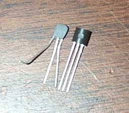
Here is what a DS18B20 looks like up close:

Basically it has three terminals: +5v, Ground, and a bi-directional data pin. You can connect up to 32 of these to a 633 by just stringing all the similar signals together on a "multi-drop" bus:

In order to get a sensor under the processor, we need some fine wire:

Solder the fine wire up to the DS18B20:

Do that for all three wires:

Then put some small heat-shrink tubing over the connections:

And shrink the tubing:

Here is the processor that I am using:

Now we are ready to see where the temp sensor is going to fit on the processor:

There is probably some adhesive out there that is made to have high thermal conductivity. For the rest of us, there is:

It probably is not a bad solution, since there will not be very much heat transferred between the sensor and the object it is sensing (because the sensor has a relatively low thermal mass) and since the layer of cured glue should be very thin, the overall thermal resistance of the joint should not be too great. If you are queasy about gluing something to your processor, this is probably not the project for you. Put a small drop of cyanoacrylate adhesive on the sensor and stick that baby smack dab in the middle of the processor:

Now it is time for another test fit:

I did not think about the heat-sink clip, so I had to angle the wires towards the corner of the processor to miss it:

This looks like it will work OK:

Now it is time to connect the next sensor in the string. The larger wire I use here is 24 gauge. 26 gauge would certainly be fine and be less bulky. Start by twisting the wires:

I found it was easiest to pre-solder the wires to each other:

Then solder them to the DS18B20:

Do all three, adding the heat-shrink tubing as you go:

Then cut some larger heatshrink tubing to go over the whole assembly:

And shrink it:

Now we are ready to mount the sensor on the heat-sink:

Drop of glue at the ready:

And it is in place:

It is fairly important to twist the wires. first off, it makes them look nicer, and second off it can reduce the interference picked up on the data line from the electrically noisy PC environment. One last test-fit on the motherboard, looks OK:

Now you basically keep adding sensors along the string wherever you want to read a temperature. Same sequence of strip and solder:

and then cover:

and shrink:

I put one on the chipset:

The video card heatsink and RAM:

The incoming airflow just after the front panel fan:

On the hard drive, which is probably doomed anyway:


On the power supply. This was supposed to measure the temperature of the air going into the power supply, but I mounted it to the case of the power supply, and I think the case is heated by the big heatsinks inside the power supply, so it is really more of a "power supply case temp" sensor:

Finally, there is a sensor that reads the temperature of the power supply's exhaust air:

Then all that is left is to connect the string to the 633. You really do not want to use a "fan" connector for this, (no matter how tempting) because if you put the 12v intended for a fan onto your sensor string, you will probably toast all of your sensors.

I found one nifty thing about this motherbooard:

It has a COM2 on the inside of the case. Alas, the Micron BIOS does not allow it to be enabled. I later found a BIOS that turns COM2 on, but now accounting will not let me at the machine. Ungrateful louts.
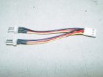
Because the 633 is mounted in a drive bay, it may be too far from the fans. Luckily I had a few 3-pin extendor cables https://www.crystalfontz.com/product/wrfanx01
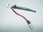
Now all that is left is to wire up the 633 to power. This is simple, since you just use a standard floppy power connector. If you are out of floppy connectors you can get a 3-Pin to 4-Pin Adapter:
Well, this post covers some ideas of physically installing the temperature sensors. I plan to modify 633_WinTest to add temperature logging capability. When I do, I'll post the results here.
Next up is to identify how the sensors correspond to the sensor numbers used by the 633. Basically you need to hook up the 633 and 633_Wintest and have it display & update all the temperatures. Then heat (or cool) each sensor and record which temperature changes on-screen. From there you can make a table that says sensor 3 is the CPU and sensor 4 is the incoming air and so on. This will never change as long as you are using the same sensor string, but you do need to manually associate the physical sensors with the sensor numbers in the 633.
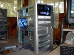
Once it was all hooked up, it did not look so bad (well, considering that it was a pretty ugly case to start with). The Micron Spitfire case has a door that covers all but the top drive bay, so I put the 633 in the top bay where it is always exposed, and then the rest of the drives are covered by the door. I used 633_WinTest to set up the 633 to continuously monitor and display the two fans along with the processor temperature sensor and one other sensor:

Use this tutorial at your own risk. If you let the magic blue smoke out of your PC, 633, DS18B20 or any thing else, that is your responsibility.
These modifications will probably "void your warranty" on a bunch of parts involved.
The guys over in accounting needed another PC. Well, I had come across some of these for $35 and I had an IBM 30G "deathstar" laying there, so I decided to throw together a PC from scratch.
One of the first things I noticed is the apparent lack of any CPU temperature sensor:
My first thought was "Who cares? It is just for accounting." Then I remembered that I had just received a bag of Dallas Semiconductor DS18B20 temperature sensors:
Of course I had a 633 and mounting bracket handy, so I thought that it would be fun to put a few temperature sensors on this ugly beast.
Here is what a DS18B20 looks like up close:
Basically it has three terminals: +5v, Ground, and a bi-directional data pin. You can connect up to 32 of these to a 633 by just stringing all the similar signals together on a "multi-drop" bus:
In order to get a sensor under the processor, we need some fine wire:
Solder the fine wire up to the DS18B20:
Do that for all three wires:
Then put some small heat-shrink tubing over the connections:
And shrink the tubing:
Here is the processor that I am using:
Now we are ready to see where the temp sensor is going to fit on the processor:
There is probably some adhesive out there that is made to have high thermal conductivity. For the rest of us, there is:
It probably is not a bad solution, since there will not be very much heat transferred between the sensor and the object it is sensing (because the sensor has a relatively low thermal mass) and since the layer of cured glue should be very thin, the overall thermal resistance of the joint should not be too great. If you are queasy about gluing something to your processor, this is probably not the project for you. Put a small drop of cyanoacrylate adhesive on the sensor and stick that baby smack dab in the middle of the processor:
Now it is time for another test fit:
I did not think about the heat-sink clip, so I had to angle the wires towards the corner of the processor to miss it:
This looks like it will work OK:
Now it is time to connect the next sensor in the string. The larger wire I use here is 24 gauge. 26 gauge would certainly be fine and be less bulky. Start by twisting the wires:
I found it was easiest to pre-solder the wires to each other:
Then solder them to the DS18B20:
Do all three, adding the heat-shrink tubing as you go:
Then cut some larger heatshrink tubing to go over the whole assembly:
And shrink it:
Now we are ready to mount the sensor on the heat-sink:
Drop of glue at the ready:
And it is in place:
It is fairly important to twist the wires. first off, it makes them look nicer, and second off it can reduce the interference picked up on the data line from the electrically noisy PC environment. One last test-fit on the motherboard, looks OK:
Now you basically keep adding sensors along the string wherever you want to read a temperature. Same sequence of strip and solder:
and then cover:
and shrink:
I put one on the chipset:
The video card heatsink and RAM:
The incoming airflow just after the front panel fan:
On the hard drive, which is probably doomed anyway:
On the power supply. This was supposed to measure the temperature of the air going into the power supply, but I mounted it to the case of the power supply, and I think the case is heated by the big heatsinks inside the power supply, so it is really more of a "power supply case temp" sensor:
Finally, there is a sensor that reads the temperature of the power supply's exhaust air:
Then all that is left is to connect the string to the 633. You really do not want to use a "fan" connector for this, (no matter how tempting) because if you put the 12v intended for a fan onto your sensor string, you will probably toast all of your sensors.
I found one nifty thing about this motherbooard:
It has a COM2 on the inside of the case. Alas, the Micron BIOS does not allow it to be enabled. I later found a BIOS that turns COM2 on, but now accounting will not let me at the machine. Ungrateful louts.
Because the 633 is mounted in a drive bay, it may be too far from the fans. Luckily I had a few 3-pin extendor cables https://www.crystalfontz.com/product/wrfanx01
Now all that is left is to wire up the 633 to power. This is simple, since you just use a standard floppy power connector. If you are out of floppy connectors you can get a 3-Pin to 4-Pin Adapter:
Well, this post covers some ideas of physically installing the temperature sensors. I plan to modify 633_WinTest to add temperature logging capability. When I do, I'll post the results here.
Next up is to identify how the sensors correspond to the sensor numbers used by the 633. Basically you need to hook up the 633 and 633_Wintest and have it display & update all the temperatures. Then heat (or cool) each sensor and record which temperature changes on-screen. From there you can make a table that says sensor 3 is the CPU and sensor 4 is the incoming air and so on. This will never change as long as you are using the same sensor string, but you do need to manually associate the physical sensors with the sensor numbers in the 633.
Once it was all hooked up, it did not look so bad (well, considering that it was a pretty ugly case to start with). The Micron Spitfire case has a door that covers all but the top drive bay, so I put the 633 in the top bay where it is always exposed, and then the rest of the drives are covered by the door. I used 633_WinTest to set up the 633 to continuously monitor and display the two fans along with the processor temperature sensor and one other sensor:
Looking for additional LCD resources? Check out our LCD blog for the latest developments in LCD technology.