Problems interfacing a 16F877 to a CFAG12864M

stash79

New member
Hi,

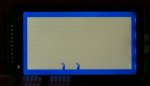
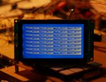
I've been trying to use a 16F877 to control one of the CFAG12864M displays, but I seem to be getting nowhere with getting the display to respond. This is the code that I have been trying to get working. Any suggestions would be greatly appreciated.

Thanks
Sean.
Code:
#include <system.h>

//Target PIC16F877 configuration word
#pragma DATA _CONFIG, _PWRTE_OFF & _BODEN_OFF & _WDT_OFF & _LVP_ON & _CPD_OFF & _DEBUG_OFF & _HS_OSC & _CP_OFF

//Set clock frequency
#pragma CLOCK_FREQ	14745000

#define row       0xB8
#define last_row  0xBF
#define col       0x40
#define last_col  63
#define first_col 0 
#define max_col   128
#define max_line  8
#define max_pos   64
#define disp_on   0x3F
#define disp_off  0x3E
#define disp_ram  0xC0

void lcd_e(bit val) // PORT AN1
{
  if (val == 0) clear_bit(porta, 1);
    else set_bit(porta, 1);
}
void lcd_cd(bit val) // PORT AN0
{
  if (val == 0) clear_bit(porta, 0);
    else set_bit(porta, 0);
}
void lcd_rw(bit val) // PORT AN2
{
  if (val == 0) clear_bit(porta, 2);
    else set_bit(porta, 2);
}
void lcd_cs1(bit val) // PORT EN0
{
  if (val == 0) clear_bit(porte, 0);
    else set_bit(porta, 0);
}
void lcd_cs2(bit val) // PORT EN1
{
  if (val == 0) clear_bit(porte, 1);
    else set_bit(porte, 1);
}
void lcd_rst(bit val) // PORT AN3
{
  if (val == 0) clear_bit(porta, 3);
    else set_bit(porta, 3);
}


// PIC16F87x defaults for hardware USART support
#define TX_PORT		0x07
#define TX_TRIS		0x87
#define TX_BIT		6
#define RX_PORT		0x07
#define RX_TRIS		0x87
#define RX_BIT		7
#define e_SPBRG		0x99
#define e_RCREG		0x1a
#define e_TXREG		0x019
#define e_TXSTA		0x98
#define e_RCSTA		0x18
#define e_TXIF_PIR	0x0c
#define e_RCIF_PIR	0x0c
#define e_TXIF_BIT	4
#define e_RCIF_BIT	5
#define MODE		(USART_reset_wdt | USART_HW)

#define bit_time 96

void toggle_enable(void)   // Toggle enable BIT on LCD screen
{

	set_bit(porta, 1);
	delay_ms(1);
	clear_bit(porta, 1);
	delay_ms(1);

}

void lcd_init(void)
{
    char tmp;
    
	lcd_cd(0);
	lcd_cs1(1);
	lcd_cs2(0);
	
	for (tmp = 1; tmp <= 2; tmp++)
	{
		portd = disp_off;
		portd = disp_ram;
		toggle_enable();
		portd = col;
		toggle_enable();
		portd = row;
		toggle_enable();
		portd = disp_on;
		toggle_enable();
		lcd_cs1(0);
		lcd_cs2(1);
	
	}
	lcd_cs1(1);
	lcd_cs2(0);

}

void lcd_clearall(void)
{
    char index, j, k;

	lcd_cd(0);
	portd = disp_off;
	toggle_enable();
	lcd_cs1(1);
	lcd_cs2(0);
	
	
    for (index = 1; index <= 2; index++)
    {
		for (j = row; j <= last_row; j++)
		{
			lcd_cd(0);
			toggle_enable();
			portd = col;
			toggle_enable();
			portd = j;
			toggle_enable();
			lcd_cd(1);
			for (k = first_col; k <= last_col; k++)
			{
				portd = 10101010b;
				toggle_enable();
			}
		
		}
    
    }
    
    lcd_cs1(0);
    lcd_cs2(1);
    lcd_cd(0);
    portd = row;
    toggle_enable();
    portd = disp_ram;
    toggle_enable();
    portd = col;
    toggle_enable();
    portd = disp_on;
    toggle_enable();
    lcd_cs1(1);
    lcd_cs2(0);
    portd = row;
    toggle_enable();
    portd = disp_ram;
    toggle_enable();
    portd = col;
    toggle_enable();
    portd = disp_on;
    toggle_enable();
    lcd_cd(1);
    lcd_cs1(1);
    lcd_cs2(0);
	

}

void interrupt( void )
{
	
	
	//Handle timer0 interrupt
	if( intcon & (1<<T0IF) )
	{
		clear_bit( intcon, T0IF ); //clear timer 0 interrupt bit
	}

	//Handle timer1 interrupt
	if( pir1 & (1<<TMR1IF) )
	{
		clear_bit( pir1, TMR1IF ); //clear timer 1 interrupt bit
	}

	//Handle timer2 interrupt
	if( pir1 & (1<<TMR2IF) )
	{
		clear_bit( pir1, TMR2IF ); //clear timer 2 interrupt bit
	}

}

#include <rs232_driver.h>

void main( void )
{

    char x, y, num;
    num = 0;


	//Configure port A
	trisa = 0x00;
	//Configure port B
	trisb = 0x00;
	//Configure port C
	//trisc = 0x00;
	//Configure port D
	trisd = 0x00;
	//Configure port E
	trise = 0x00;

	//Configure A/D pins
	adcon1 = 0x06;


	//Initialize port A
	porta = 0x00;
	//Initialize port B
	portb = 0x00;
	//Initialize port C
	//portc = 0x00;
	//Initialize port D
	portd = 0x00;
	//Initialize port E
	porte = 0x00;
	//Set Timer0 mode
	clear_bit( option_reg, T0CS ); //configure timer0 as a timer
	//Set prescaler assignment
	clear_bit( option_reg, PSA ); //prescaler is assigned to timer0
	//Set prescaler rate
	clear_bit( option_reg, PS2 ); //prescaler rate 1:2
	clear_bit( option_reg, PS1 );
	clear_bit( option_reg, PS0 );
	//Set timer0 source edge selection
	set_bit( option_reg, T0SE ); //increment on high-to-low transition on RA4/T0CKI pin

	//Set timer 1 prescaler rate
	clear_bit( t1con, T1CKPS1 ); //prescaler rate 1:1
	clear_bit( t1con, T1CKPS0 );
	//Set timer 1 mode
	clear_bit( t1con, TMR1ON ); //disable timer 1

	//Set timer 2 prescaler rate
	clear_bit( t2con, T2CKPS1 ); //prescaler rate 1:1
	clear_bit( t2con, T2CKPS0 );
	//Set timer 2 postscaler rate
	clear_bit( t2con, TOUTPS3 ); //postscaler rate 1:1
	clear_bit( t2con, TOUTPS2 );
	clear_bit( t2con, TOUTPS1 );
	clear_bit( t2con, TOUTPS0 );
	//Set timer 2 mode (enable or disable)
	clear_bit( t2con, TMR2ON ); //enable timer 2


	//Enable interrupts (Timer0)
	intcon = 0xA0;
	
	delay_ms(10000);
	
	lcd_init();
	lcd_clearall();


	//Endless loop
	uart_init(1,95);  // set high speed divisor mode and divisor value
	puts("Hello, world");
	while (1)
	{
		if (kbhit())
		{
			putc(getc());
		}
	}
		
}
Looking for additional LCD resources? Check out our LCD blog for the latest developments in LCD technology.
 
What is the voltage on Pin 3 (Vo)? Can you turn the contrast pot and see the screen go from light to dark or vice versa? Which model do you have?
 

stash79

New member
What is the voltage on Pin 3 (Vo)? Can you turn the contrast pot and see the screen go from light to dark or vice versa? Which model do you have?
I measure -6.63V on Pin 3. The contrast on the display does seem go from light to dark as I turn the pot. The model of the display I'm working with is a CFAG12864M-TMI-T#N, I have also been testing with a model CFAG12864M-YYH-T#N with the same results.
 

stash79

New member
Ok. I think I found some of where my issue was. I wasn't setting the RST line in my code so I think it was always in a reset state. The display is at least reacting to the program now. Though still not displaying what I want to it to.

Thanks.
 
Well, your code is certainly much more readable now. I wonder about the

uart_init(1,95);
puts("Hello, world");

Is that to let you know that the LCD part is executed (in case the LCD doesn't let you know)? If you need more help, post back.
 

stash79

New member
I do have the PIC mcu connected to a PC via a serial port connection so I can verify that it is at least executing. Unfortunately I seem to be getting nowhere fast.

I'm still at a loss as to why it doesn't seem to be working correctly. the lcd_init and lcd_clearall routines manage to change a few pixels on the screen consistently but I haven't been able to work out why it is placing them where it is. Any attempts I make at trying to write at other locations seem to fail. I've attached an image of all I've been able to get the display to show so far.

This also includes some changes I've made to the code.

Code:
#include <system.h>

//Target PIC16F877 configuration word
#pragma DATA _CONFIG, _PWRTE_OFF & _BODEN_OFF & _WDT_OFF & _LVP_ON & _CPD_OFF & _DEBUG_OFF & _HS_OSC & _CP_OFF

//Set clock frequency
#pragma CLOCK_FREQ	14745000

#define row       10111000b
#define last_row  10111111b
#define col       01000000b
#define last_col  63
#define first_col 0 
#define max_col   128
#define max_line  8
#define max_pos   64
#define disp_on   00111111b
#define disp_off  00111110b
#define disp_ram  11000000b

void lcd_e(bit val) // PORT AN1
{
  if (val == 0) clear_bit(porta, 1);
    else set_bit(porta, 1);
}
void lcd_cd(bit val) // PORT AN0
{
  if (val == 0) clear_bit(porta, 0);
    else set_bit(porta, 0);
}
void lcd_rw(bit val) // PORT AN2
{
  if (val == 0) clear_bit(porta, 2);
    else set_bit(porta, 2);
}
void lcd_cs1(bit val) // PORT EN0
{
  if (val == 0) clear_bit(porte, 0);
    else set_bit(porta, 0);
}
void lcd_cs2(bit val) // PORT EN1
{
  if (val == 0) clear_bit(porte, 1);
    else set_bit(porte, 1);
}
void lcd_rst(bit val) // PORT AN3
{
  if (val == 0) clear_bit(porta, 3);
    else set_bit(porta, 3);
}


// PIC16F87x defaults for hardware USART support
#define TX_PORT		0x07
#define TX_TRIS		0x87
#define TX_BIT		6
#define RX_PORT		0x07
#define RX_TRIS		0x87
#define RX_BIT		7
#define e_SPBRG		0x99
#define e_RCREG		0x1a
#define e_TXREG		0x019
#define e_TXSTA		0x98
#define e_RCSTA		0x18
#define e_TXIF_PIR	0x0c
#define e_RCIF_PIR	0x0c
#define e_TXIF_BIT	4
#define e_RCIF_BIT	5
#define MODE		(USART_reset_wdt | USART_HW)


#define bit_time 96	// 115200 baud at 40MHz

void toggle_enable(void)
{

	set_bit(porta, 1);
	delay_100us(50);
	clear_bit(porta, 1);
	delay_100us(50);

}

void lcd_init(void)
{
    char tmp;
    
	lcd_cd(0);
	lcd_cs1(1);
	lcd_cs2(0);
	
	for (tmp = 1; tmp <= 2; tmp++)
	{
		portd = disp_off;
		portd = disp_ram;
		toggle_enable();
		portd = col;
		toggle_enable();
		portd = row;
		toggle_enable();
		portd = disp_on;
		toggle_enable();
		lcd_cs1(0);
		lcd_cs2(1);
	
	}
	lcd_cs1(1);
	lcd_cs2(0);

}

void lcd_clearall(void)
{
    char index, j, k;

	lcd_cd(0);
	portd = disp_off;
	toggle_enable();
	lcd_cs1(1);
	lcd_cs2(0);
	
	
    for (index = 1; index <= 2; index++)
    {
		for (j = row; j <= last_row; j++)
		{
			lcd_cd(0);
			toggle_enable();
			portd = col;
			toggle_enable();
			portd = j;
			toggle_enable();
			lcd_cd(1);
			for (k = first_col; k <= last_col; k++)
			{
				portd = 11111111b;
				toggle_enable();
			}
		
		}
    
    }
    
    lcd_cs1(0);
    lcd_cs2(1);
    lcd_cd(0);
    portd = row;
    toggle_enable();
    portd = disp_ram;
    toggle_enable();
    portd = col;
    toggle_enable();
    portd = disp_on;
    toggle_enable();
    lcd_cs1(1);
    lcd_cs2(0);
    portd = row;
    toggle_enable();
    portd = disp_ram;
    toggle_enable();
    portd = col;
    toggle_enable();
    portd = disp_on;
    toggle_enable();
    lcd_cd(1);
    lcd_cs1(1);
    lcd_cs2(0);
	

}


void interrupt( void )
{
	
	
	//Handle timer0 interrupt
	if( intcon & (1<<T0IF) )
	{
		clear_bit( intcon, T0IF ); //clear timer 0 interrupt bit
	}

	//Handle timer1 interrupt
	if( pir1 & (1<<TMR1IF) )
	{
		clear_bit( pir1, TMR1IF ); //clear timer 1 interrupt bit
	}

	//Handle timer2 interrupt
	if( pir1 & (1<<TMR2IF) )
	{
		clear_bit( pir1, TMR2IF ); //clear timer 2 interrupt bit
	}

}

#include <rs232_driver.h>

void main( void )
{

    char x, y, num;
    num = 0;


	//Configure port A
	trisa = 0x00;
	//Configure port B
	trisb = 0x00;
	//Configure port C
	//trisc = 0x00;
	//Configure port D
	trisd = 0x00;
	//Configure port E
	trise = 0x00;

	//Configure A/D pins
	adcon1 = 0x06;


	//Initialize port A
	porta = 0x00;
	//Initialize port B
	portb = 0x00;
	//Initialize port C
	//portc = 0x00;
	//Initialize port D
	portd = 0x00;
	//Initialize port E
	porte = 0x00;
	//Set Timer0 mode
	clear_bit( option_reg, T0CS ); //configure timer0 as a timer
	//Set prescaler assignment
	clear_bit( option_reg, PSA ); //prescaler is assigned to timer0
	//Set prescaler rate
	clear_bit( option_reg, PS2 ); //prescaler rate 1:2
	clear_bit( option_reg, PS1 );
	clear_bit( option_reg, PS0 );
	//Set timer0 source edge selection
	set_bit( option_reg, T0SE ); //increment on high-to-low transition on RA4/T0CKI pin

	//Set timer 1 prescaler rate
	clear_bit( t1con, T1CKPS1 ); //prescaler rate 1:1
	clear_bit( t1con, T1CKPS0 );
	//Set timer 1 mode
	clear_bit( t1con, TMR1ON ); //disable timer 1

	//Set timer 2 prescaler rate
	clear_bit( t2con, T2CKPS1 ); //prescaler rate 1:1
	clear_bit( t2con, T2CKPS0 );
	//Set timer 2 postscaler rate
	clear_bit( t2con, TOUTPS3 ); //postscaler rate 1:1
	clear_bit( t2con, TOUTPS2 );
	clear_bit( t2con, TOUTPS1 );
	clear_bit( t2con, TOUTPS0 );
	//Set timer 2 mode (enable or disable)
	clear_bit( t2con, TMR2ON ); //enable timer 2


	//Enable interrupts (Timer0)
	intcon = 0xA0;
	
	delay_ms(10000);
	
	lcd_rst(0);       // Reset the display
	delay_ms(1000);
	lcd_rst(1);
	delay_ms(1000);
	lcd_rst(0);
	delay_ms(1000);
	lcd_rst(1);
	delay_ms(1000);
	
	lcd_cd(0);        // Try and fill a pattern on part of the display
	lcd_rw(0);
	lcd_cs1(1);
	lcd_cs2(0);
	portd = disp_off;
	toggle_enable();
	portd = disp_ram;
	toggle_enable();
	portd = col;
	toggle_enable();
	portd = row;
	toggle_enable();
	
	lcd_cd(1);
	lcd_rw(0);
	for (x = 0; x < 63; x++) 
	{
	  portd = 10101010b;
	  toggle_enable();
	
	}
	
    portd = row;
    toggle_enable();
    portd = disp_ram;
    toggle_enable();
    portd = col;
    toggle_enable();
    portd = disp_on;
    toggle_enable();
	
	//lcd_init();
	//lcd_clearall();


	//Endless loop
	uart_init(1,95);  // set high speed divisor mode and divisor value
	puts("Hello, world");
	while (1)
	{
		if (kbhit())
		{
			putc(getc());
		    lcd_init();            // Test with these routines to see if the display does 
	        lcd_clearall();        // anything at all. these only manage to light up a few pixels on
                                              // the display haven't been able to figure out why or when it is placing
                                              // them on the screen.
	    
		}
	}
		
}
 

Attachments

I imported your code into my test setup (using a Zilog Z8), and changed a few things to make it compatible.

I don't have a CFAG12864"M", I have the "B". The difference seems to be the active level for the chip selects, LOW for "B", HIGH for "M" (as I read the data sheet), due to a slightly different controller chip.

Anyway, with your code, I can write patterns to the screen with no problem. If you want to see my modified code, let me know, else I won't bother posting it.
 

Attachments

Last edited:

stash79

New member
Yay. Its finally doing something. I think I figured out where my issue was. I was only trying to manipulate a single side of the display to start off with. And I had the display oriented backwards from how I thought it was.

I'll post my code after I have something useable. Maybe it will be helpful for others.

Thanks for the help.
 

stash79

New member
Here is the code for anyone who wants to take a look. I haven't done any work on optimizing the timing so its not the fastest thing in the world. Use for whatever you want I've attached an image of the test pattern that it displays for reference. This is written for the sourceboost PIC C Compiler.

Code:
#include <system.h>

//Target PIC16F877 configuration word
#pragma DATA _CONFIG, _PWRTE_OFF & _BODEN_OFF & _WDT_OFF & _LVP_ON & _CPD_OFF & _DEBUG_OFF & _HS_OSC & _CP_OFF

//Set clock frequency
#pragma CLOCK_FREQ	14745000

#define row       10111000b
#define last_row  10111111b
#define col       01000000b
#define last_col  63
#define first_col 0 
#define max_col   128
#define max_line  8
#define max_pos   64
#define disp_on   00111111b
#define disp_off  00111110b
#define disp_ram  11000000b

void lcd_e(bit val) // PORT AN1
{
  if (val == 0) clear_bit(porta, 1);
    else set_bit(porta, 1);
}
void lcd_cd(bit val) // PORT AN0
{
  if (val == 0) clear_bit(porta, 0);
    else set_bit(porta, 0);
}
void lcd_rw(bit val) // PORT AN2
{
  if (val == 0) clear_bit(porta, 2);
    else set_bit(porta, 2);
}
void lcd_cs1(bit val) // PORT EN0
{
  if (val == 0) clear_bit(porte, 0);
    else set_bit(porte, 0);
    //delay_ms(100);
}
void lcd_cs2(bit val) // PORT EN1
{
  if (val == 0) clear_bit(porte, 1);
    else set_bit(porte, 1);
    //delay_ms(100);
}
void lcd_rst(bit val) // PORT AN3
{
  if (val == 0) clear_bit(porta, 3);
    else set_bit(porta, 3);
}

void toggle_enable(void)
{
	delay_ms(1);
	set_bit(porta, 1);
	delay_ms(1);
	clear_bit(porta, 1);

}

void lcd_init(void)
{
    char tmp;
    
	lcd_cd(0);
	lcd_cs1(1);
	lcd_cs2(0);
	
		portd = disp_off;
		toggle_enable();
		portd = disp_ram;
		toggle_enable();
		portd = col;
		toggle_enable();
		portd = row;
		toggle_enable();
		portd = disp_on;
		toggle_enable();
     	
     	lcd_cd(0);
		lcd_cs1(0);
		lcd_cs2(1);

		portd = disp_off;
		portd = disp_ram;
		toggle_enable();
		portd = col;
		toggle_enable();
		portd = row;
		toggle_enable();
		portd = disp_on;
		toggle_enable();


	lcd_cs1(0);
	lcd_cs2(1);

}

void main( void )
{
    char x, y, c, num;
    num = 0;


	//Configure port A
	trisa = 0x00;
	//Configure port B
	trisb = 0x00;
	//Configure port C
	//trisc = 0x00;
	trisc = trisc | 00111111b;
	//Configure port D
	trisd = 0x00;
	//Configure port E
	trise = 0x00;

	//Configure A/D pins
	adcon1 = 0x06;


	//Initialize port A
	porta = 0x00;
	//Initialize port B
	portb = 0x00;
	//Initialize port C
	portc = 0x00;
	//Initialize port D
	portd = 0x00;
	//Initialize port E
	porte = 0x00;
	//Set Timer0 mode
	clear_bit( option_reg, T0CS ); //configure timer0 as a timer
	//Set prescaler assignment
	clear_bit( option_reg, PSA ); //prescaler is assigned to timer0
	//Set prescaler rate
	clear_bit( option_reg, PS2 ); //prescaler rate 1:2
	clear_bit( option_reg, PS1 );
	clear_bit( option_reg, PS0 );
	//Set timer0 source edge selection
	set_bit( option_reg, T0SE ); //increment on high-to-low transition on RA4/T0CKI pin

	//Set timer 1 prescaler rate
	clear_bit( t1con, T1CKPS1 ); //prescaler rate 1:1
	clear_bit( t1con, T1CKPS0 );
	//Set timer 1 mode
	clear_bit( t1con, TMR1ON ); //disable timer 1

	//Set timer 2 prescaler rate
	clear_bit( t2con, T2CKPS1 ); //prescaler rate 1:1
	clear_bit( t2con, T2CKPS0 );
	//Set timer 2 postscaler rate
	clear_bit( t2con, TOUTPS3 ); //postscaler rate 1:1
	clear_bit( t2con, TOUTPS2 );
	clear_bit( t2con, TOUTPS1 );
	clear_bit( t2con, TOUTPS0 );
	//Set timer 2 mode (enable or disable)
	clear_bit( t2con, TMR2ON ); //enable timer 2


	//Enable interrupts (Timer0)
	//intcon = 0xA0;
	
	delay_ms(10000);
	
	lcd_rst(0);       // Reset the display
	delay_ms(100);
	lcd_rst(1);
	delay_ms(100);
	lcd_rst(0);
	delay_ms(100);
	lcd_rst(1);
	delay_ms(100);
	
	lcd_init();
	delay_ms(100);
	delay_ms(100);

    y = 0;


    for (c = 0; c <= 7; c++)
    {


    lcd_cd(0);
    lcd_rw(0);
    lcd_cs1(0);
    lcd_cs2(1);
    portd = disp_ram;
    toggle_enable();
    portd = col;
    toggle_enable();
    portd = row + c;
    toggle_enable();

    lcd_cd(1);
    lcd_rw(0);

    for (x = 0; x <= 63; x++)
    {
        portd = x;
        toggle_enable();
    }
    lcd_cd(0);
    lcd_rw(0);
    lcd_cs1(1);
    lcd_cs2(0);
    portd = disp_ram;
    toggle_enable();
    portd = col;
    toggle_enable();
    portd = row + c;
    toggle_enable();

    lcd_cd(1);
    lcd_rw(0);

    for (x = 64; x <= 127; x++)
    {
        portd = x;
        toggle_enable();
    }
    y = y + 8;

    }


	while (1)
	{
	}
		
}
 

Attachments

Top