Problems Initializing CFAH160B character LCD with PIC18F452

Melancholy13

New member
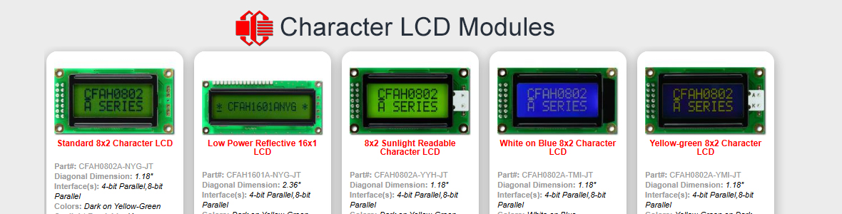
Display: CFAH1604B-TMI-ET
MCU : PIC18F452
Clock : 25Mhz

Intro:
I'm working on a hardware project, and wanted to try using an LCD for outputting information. As such I chose the above mentioned character display. This is my first time trying to interface with a display of any type other than simple LEDs so I apologize in advance if my problem is a simple one.

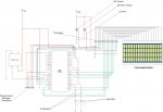
I have attached both a hardware schematic of my current PIC-to-LCD configuration, as well as my .c file that I am using to try and initialize and output to the screen. I have created the following functions in my code:
LCDCharacterInitialize(void) --LCD initialization function
ICommandThee(unsigned int) --Write command function
SpitItOut(unsigned int) --Display character string function
DummyHalt(void) --Dummy loop used to halt the program for debugging

A few additional details on each of the functions are available in my code file attached.


Problem:
It does not appear that the screen is initializing. When I turn the circuit on, the screen lights up and I can see two lines of squares. I can adjust the intensity of both the squares and the backlight using the attached trimpots. I am using the Delay.h file supplied in MPlab to generate my delay times needed. I am pretty sure that I have calculated out my delay times properly, but am not 100% sure anymore since I am not getting any type of an output on the display.

I have tested the PIC18F452 separate from the LCD to ensure that it is functioning. This test included using a pair of LEDs and jumpering them to various ports on the PIC (i.e. RC0-RC7, RD0-RD7, etc.) I did not check every port to make sure it was functional, but I did test a few, just to make sure that the PIC was indeed functioning.

I am out of ideas as what to test, or look at and am hoping for some input as to things to try. I am sure it is just some little thing that I am missing, but I am at my wits end as to what it is.

Thanks in advance to any who may reply.
Looking for additional LCD resources? Check out our LCD blog for the latest developments in LCD technology.
 

Attachments

The problem that seems most glaring to me is your command and data output functions. You are using the statement:

PORTD = data >> 8;

where the data/command is an 8 bit value. By shifting right 8 times, you are throwing out the lower 8 bits, which contain the data, and outputting the upper 8 bits, which are all 0s. Thats why nothing works. Take out the ">> 8", and try it. Also, no point in passing a 16 bit unsigned int, when all values are 8 bit. Use "unsigned char".

Also, I am cringing at the use of a 10K pot for backlight control, especially with no other current limiting resistor. All of the useful action of the pot is at one end, and when you hit the upper end of the pot, there is no current limit, so you could toast the backlight. A 100 ohm pot and a 20 ohm series resistor would probably be a better choice.
 
Last edited:

Melancholy13

New member
Thanks for the reply.

Thank you very much, Cosmicvoid, for the help. You gave me some new ground to work with. What you said about shifting the bits made sense, and checking the voltages during a breakpoint in my code confirmed that the data bus had all 0s on it. I have changed my variable type to unsigned char instead of unsigned int, and removed the right shift from my code. I have also made a few changes to the code, namely simplifying some it (removing commented code and changing some of my binary values to hex values like when I'm initializing the location of the cursor.)

I made two attempts and these were the results.

1st Attempt
Once making the suggested changes I tried the code and the screen still did not initialize

2nd Attempt
I went ahead and changed my delay values to very large values, figuring that it was better to wait way to long then not enough (this is also when I cleaned up the code a bit), and that appeared to do something. The two lines that display all squares went away, but still no output. Also, it appeared that the other two lines partially initialized. It appeared that only the first three rows of pixels in each character section initialized. I can attach a picture to another post if this would be helpful.

I decided to not test it any further until I make the recommended changes to the wiring for the back light. I should have this done later on tonight, but I have to go and pick up some trimpots.
 

Attachments

Glad you are making progress, but by the looks of your new code you have introduced new errors. Specifically, in your command and data output functions, you are not setting RS_PIN before the E_PIN strobe.
Code:
void ICommandThee(unsigned char instruction)
{
	PORTD = instruction;
	RS_PIN = 0;	// make sure RS is in proper state
	/*Tpw requirements state 140ns (140000us) as the minimum pulse width.  The pulse width in this system is 12.5us so 
	this should be fine*/
	E_PIN = 1;
	Delay here for 200 nS
	E_PIN = 0;
	Delay10TCYx(10);
}
void SpitItOut(unsigned char character)
{
	PORTD = character;
	RS_PIN = 1;	// make sure RS is in proper state
	E_PIN = 1;
	Delay here for 200 nS
	E_PIN = 0;
//	RS_PIN = 0;  // don't need to do this
	Delay10TCYx(50);
}
Despite your assertion that the "pulse width in this system is 12.5us", I see nothing in your code to make me believe that, so you should probably add a few hundred nS delay between E going high -> low.

One other thought: I see that the data sheet calls for only two repetitions of the function set command (0x3C), but other controllers commonly call for at least three function set commands in a row when initializing. So if you add another one, it may help, I don't know for sure.

Also, when you command to set the cursor position, you aren't setting bit 7 of the command high. The commands should be:
line 1 - 0x80~0x8F
line 2 - 0xC0~0xCF
line 3 - 0x90~0x9F
line 4 - 0xD0~0xDF

When you get these things working, then we can work on testing the busy flag, so you can get rid of the clunky delays.
 

Melancholy13

New member
Thanks again Cosmicvoid. Your help is greatly appreciated. One thing I forgot to mention in the last post was that my results of the screen doing something were sporadic. I have not been able to repeat the output once since.

In the mean time I did rewire my screen using the suggestions you mad in your first reply. I also made the appropriate changes to how I was setting the cursor location.

One thing I am a little confused on though is the comment on the RS_PIN. I was looking at the timing diagrams in the datasheet and it appears that RS is a don't-care value for Write option (as far is writing from the PIC to the screen as an internal command anyways.) Is this correct? According to the timing diagram, RW does need to be low for the time that I am sending data from the PIC to the screen.

The way I am reading the timing diagram does contradict the values listed in the Instruction Code Table, so I will assume that RS must be 0 unless trying to access RAM on the screen (such as in the SpitItOutFunction.)

I have attached my modified code. At the end of the code I also have a commented section explaining how I calculated my pulse width and delay times.

I'm excited and looking forward to getting the screen working!! Unfortunately I still just seem to be missing something. :)
 

Attachments

Last edited:
One thing I am a little confused on though is the comment on the RS_PIN. I was looking at the timing diagrams in the datasheet and it appears that RS is a don't-care value for Write option (as far is writing from the PIC to the screen as an internal command anyways.) Is this correct?
No. The state of RS determines whether you are accessing the command register or the data ram, 0 = command, 1 = data.

You say
Clock Speed 25MHz -> 25x10^6 cycles/second
Therefore 1 cycle = 25x10^-6 seconds or 25us
1 cycle = 1 / 25*10^6 = 40 nS, not 25 uS. So a "pulse" would be 20 nS. But I think this has no bearing on your code, unless you are using raw clock output for something.

Your Tcy calcs agree with the 40 nS value.

I don't see any obvious problem in your code. Your delays seem to be plenty long enough, in fact much longer that mentioned in the comments. Do you have a way to verify that your signals and delays are what you think they are? Like an oscilloscope?

While it seems your init function should work OK, it seems to not work, based on what you say. Maybe your init isn't working because you are trying to use the "big" font, which is probably not usable on that panel.

Here is the init sequence I am using in another project that has a 16x4 character LCD, in 8 bit mode. You could try this sequence and see if it makes any difference.
Code:
	command(0x30);		// init command byte
	Delay(591);		// 4.1 mS @ 6.944 uS per count
	command(0x30);
	Delay(15);		// 100 uS @ 6.944 uS per count
	command(0x30);
	Delay(15);		// 100 uS @ 6.944 uS per count

	LCDCmd(0x38);		// 8 bit I/F, 2 line, 8 dot font
	LCDCmd(8);		// display off, cursor off, blink off
	LCDCmd(CLEAR);		// clear and home
	LCDCmd(6);		// increment cursor, no shift
	LCDCmd(12);		// display on
The first 3 function set commands have delays because the busy flag cannot be checked. The rest of the commands, using LCDCmd(), do busy checking.
 

Melancholy13

New member
1 cycle = 1 / 25*10^6 = 40 nS, not 25 uS. So a "pulse" would be 20 nS.
That's what I get for not using my calculator to check myself. I got careless with that calculation and as a result, made a very stupid mistake. Thank you very much for catching that for me.:eek:

Do you have a way to verify that your signals and delays are what you think they are? Like an oscilloscope?
I do have a DMM, but no oscilloscope. I should be able to use one at the university on Monday, but I have to wait until there are no classes utilizing the room. In the mean time I guess I will just keep going over the code and wiring to make absolutely sure there isn't anything else I missed.

I tried your init sequence (thanks for providing that by the way) but it didn't seem to work.

Until I can check the signals and what not with the oscilloscope on Monday, I guess I am going to have to assume that there is something wrong with my ICommandThee() function and/or my initialization sequence.

I like your sequence setup. If I understand it correctly, it should do the following
1. switch the screen to 4 line mode
2. switch back to 2 line mode
3. turn off the display (as well as the cursor blink and shift)
4. clear the screen
5. set the cursor
6. turn the display back on

I also like the fact that you have a separate command function for checking your busy flag. Once I can see that my initialization sequence is definitely being completed, then I'll see about writing a similar function.:D
 
I'm sorry that you still aren't able to init successfully. That suggests that something is wrong with the wiring or the control signal timing.

Have you tried removing power to the LCD between attempts? I think that sometime in the distant past, I recall reading that the HD44780 type controllers cannot change the Function Set value, once it has been set, without resetting the controller, which means power down, since it has no reset input. I don't know if that is still true with the HD44780 compatibles, or if that applies to this situation. The reason I mention it is in case the display is getting set to 4-bit mode or something, you might be stuck there until the controller is reset.

In my code, the first 3 repetitions of 0x30 are intended to establish the interface length (8-bit), then the last one sets the line mode and font bits. I also have other programs where all 4 repetitions use 0x38, and that works OK, too.

One thing I notice in your code, in the CharLCDInit() function, is that you set E_PIN to 1 as the first statement. What is that for? I think you ought to remove that, unless you have a good reason for it.

Another suggestion, for your delay functions. Instead of having multiples of 10 * Tcy, it might make things easier to have multiples that allow direct time values, such as:
Delay_uS(Value) = 6*Tcy*Value // value is in microseconds
Delay_mS(Value) = 6250*Tcy*Value // value is in milliseconds

One last item: in your code you have
Code:
#define RS_PIN 	PORTCbits.RC0	//pin 4 on display to pin16 on pic
#define RW_PIN	PORTCbits.RC1	//pin 5 on display to pin17 on pic
#define E_PIN 	PORTCbits.RC2	//pin 6 on display to pin18 on pic
but the pic pin numbers in the comments are wrong. The pin connections in the schematic seem to be right, though its very hard to read the small pin name text in your attached diagram. Just to be sure you check your wiring.

Afterthought: when you check signals, with a meter or a scope, do the measurement at the display pins, to make sure that you can see the effect of noise, ringing, etc.
 
Last edited:

Melancholy13

New member
Sorry for the delayed reply and update. I was starting to get frustrated with the LCD so I moved on to another project for the weekend. It turns out that I was never able to get to the oscilloscope to test my outputs so I will now have to wait until Thursday for my next access.

Have you tried removing power to the LCD between attempts?
I did not actually think of that, and that may explain some of the issues I've been having. I had an "I" output to the screen one time. I made the mistake of making a couple of changes to my SpitItOut() function, thinking that that was where the issue was and then recompilling and testing. When that didn't work I made some other changes and before I knew it I could not reproduce any output at all. I will be sure to turn off the entire circuit before running each new batch of code from now on. Also, I will make sure to save a copy of code that produces any type of output BEFORE trying to "fix" it.

but the pic pin numbers in the comments are wrong
This is true. That was actually one of the very first errors I noticed (actually before I ever started this post.) I made the appropriate changes to the circuit, but forgot to change the comments. The circuit is wired as the schematic shows, not as the comments say. I did check it again though, just to be sure. I appreciate you taking the time to check out my schematics and code in such detail.

Another suggestion, for your delay functions. Instead of having multiples of 10 * Tcy, it might make things easier to have multiples that allow direct time values, such as:
Delay_uS(Value) = 6*Tcy*Value // value is in microseconds
Delay_mS(Value) = 6250*Tcy*Value // value is in milliseconds
Actually I would like to do that, but was not aware that such functions were available. I was using the Delay10TCYx() functions because I am using the C18 compiler from Microchip, since they have a free version available. After doing a little bit of research it appears that the Delay_ms() & Delay_uS() functions are available from the BoostC compiler package. I will have to look into trying it out. Thank you very much for the suggestion. In the mean time, perhaps I will make my own uS functions using the calculated Tcy value for my system (as you suggested... I just now figured that out :eek:.) If nothing else, it will make the intent of the code a little more readable

I am going to be working on this again for awhile tonight. I have taken a good break from the screen and am now attacking it again with newfound excitement and spirits. Thank you again cosmicvoid for your help and suggestions. I will post my results soon.:D
 
Last edited:
Top