
I've started a project of turning an old stereo receiver into an HTPC.
I want to display Kodi information on the front so I bought a couple 256x64 Grayscale Graphic OLED's (CFAL25664C0-021M-W)
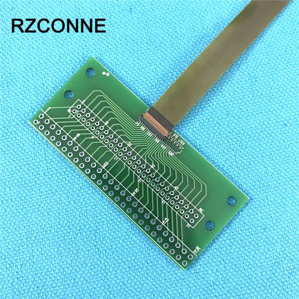
And a couple connector boards to attach them to an Arduino.
 www.aliexpress.com
I've never done anything like this before and was incredibly excited to learn about Arduinos, displays, and how they work together.
I bought that OLED because it said it was I2C. Surely if it only needs 4 wires, I could figure it out.
After looking through the Datasheet and the Arduino/Seeeduino Demo Code I thought I learned how to do it.
OLED Arduino
Pin Pin
18 to D9
19 to D10
22 to D13
23 to D11
3.3v to 12or15
Ground 10or11
But I was mistaken. Wiring it like that doesn’t work.
I'm hoping a kind and knowledgeable soul here would straight up tell me which pins on the OLED go to which pins in the Arduino Micro or Uno.
Thanks in advance to those who are helpful.
I want to display Kodi information on the front so I bought a couple 256x64 Grayscale Graphic OLED's (CFAL25664C0-021M-W)
And a couple connector boards to attach them to an Arduino.
4.3US $ |31Pin Connector 2.0mm 2.54mm cable to 0.3mm Pitch DIP FPC LVDs MIPI Adapter with FPC Flexible Flat Cable 60mm 150mm choose|Computer Cables & Connectors| - AliExpress
Smarter Shopping, Better Living! Aliexpress.com
I've never done anything like this before and was incredibly excited to learn about Arduinos, displays, and how they work together.
I bought that OLED because it said it was I2C. Surely if it only needs 4 wires, I could figure it out.
After looking through the Datasheet and the Arduino/Seeeduino Demo Code I thought I learned how to do it.
OLED Arduino
Pin Pin
18 to D9
19 to D10
22 to D13
23 to D11
3.3v to 12or15
Ground 10or11
But I was mistaken. Wiring it like that doesn’t work.
I'm hoping a kind and knowledgeable soul here would straight up tell me which pins on the OLED go to which pins in the Arduino Micro or Uno.
Thanks in advance to those who are helpful.
Looking for additional LCD resources? Check out our LCD blog for the latest developments in LCD technology.
")