LCD CFAH2002AYYHJP - Character Display Problems

cjdellaporta

New member
Hello,

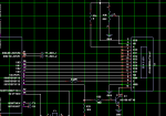
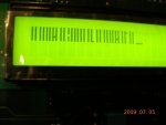
I am currently using an CFAH2002AYYHJP Crystal Fontz display and a Microchip PIC18F4321 microcontroller. The LCD is operating in 4 bit parallel mode. I am able to initialize the LCD and send commands successfully; however, when I attempt to display characters, the display is showing strange characters (random lines), and not the characters shown in the data sheet. I have tried two different LCDs and do not believe that I have any hardware issues. Any suggestions will be greatly appreciated.

Thanks.

CJ
Looking for additional LCD resources? Check out our LCD blog for the latest developments in LCD technology.
 
Could be a problem in your code. Why don't you attach a file showing your routines for writing to the display, for both commands and characters.

Might also be a wiring error (switched bits, shorted bits), or timing problem, or noisy signals. The more you can tell about your hookup, the easier it will be to make suggestions.
 

cjdellaporta

New member
Attachement

Hello,

I have attached a zip file with some code and a ".jpg". These file should provide a little more insight. Like I stated previously. I am able to initialize the display and pass commands (cursor commands) successfully, but I am having problems displaying characters. Thanks for the help.

CJ
 

Attachments

I have looked at your code, and it seems that you haven't included your "main()" function, so I can't see what you are doing beyond the initialization section. Also, your port pin assignments aren't shown, so I am assuming that the D3~D0 bits of your data port are wired to the D7~D4 bits of the display input bus. I also assume that you are using a different port to control the E, RS, RW signals.

Basically, your code seems OK, except for a few things that seem suspicious:

1. You make this definition: #define LCD_LINE_FONT 0b00101100 //0x2C
but you don't use it. Instead you use the value 0b00101000 //0x28
which is good, because the display doesn't have a 5x11 font, so you must choose the 5x8 font, which you have done.

2. You command the display OFF by sending 0b00001000 //0x08
but I do not see any command to set the display back to ON. That may be in the part of the code you did not include.

3. You have this comment: /* Function set - Entry Mode Select */
but the command you send in this block is 0b00000010 //0x02, which is actually a HOME command.

Without seeing more of your code (or ALL of it) I can't pinpoint a problem that would cause your symptom. What you might do next is send a sequence of characters, like 0 thru 9 and A thru J, to see if the resulting display shows any clues about what is happening to the data. Since the display is not showing a row of dark blocks on the top line, it seems your init sequence is working.

After you do this block: /* Set interface to 4-bit mode */, you could start using your "void LCD_Instruction(unsigned char command)" function to test the busy flag, instead of using delays for the remainder of the init commands.

Without more info, I can't make any good suggestions.
 

jmrosino

New member
Hello cosmicvoid,

I am working with CJ on this project. I have some additional information for you. Thank you for taking time to review our issue. We really appreciate your help.

I have attached a screen grab of our schematic that shows the electrical connections to the display. Good call on the entry mode section. I just looked at the data sheet again, and there is an error in the flow chart for 4 bit instructions. I have corrected this section of code so we now send 0b00000110 (increment AC and disable shift). I will add a section of code to turn the display back on. The flow chart doesn't list this instruction as part of the initialization routine... but it definitely makes sense to add this.

Also, a quick note... I noticed the data pins on the LCD (DB7-DB4) are always high (pulled up to +5V) when I go to read the display. We change the TRISD register for inputs, and the lines pull high. They seem to have an internal pull up resistor. Does this seem right? I am trying to read the register for the address counter value, but it keeps returning 0xFF.

Here is the section of code we have in main to test sending characters:

LCD_Instruction(LCD_CLEAR_DISPLAY);
LCD_wData(LCD_3);

We call this function after pressing a button on the PCB.

Thanks for your help.

-Jeff
 

Attachments

Since you didn't attach any more code, I am still having to make presumptions, which is not a good way to provide help.
I have attached a screen grab of our schematic that shows the electrical connections to the display.
Well, that helps a bit, as I see you are using one port for both data and control. This explains a lot about how your code is written. One suggestion, just in the interest of maximum robustness, for your "LCD_Bits()" function:
Code:
void LCD_Bits(unsigned char data)
{
	LATD &= 0b11110000;
	LATD |= [b](data & 0x0F);  // prevent data from corrupting control bits[/b]
}
I will add a section of code to turn the display back on.
OK, but I don't know why the data sheet suggests to turn it off, as there is no need to do so.
Also, a quick note... I noticed the data pins on the LCD (DB7-DB4) are always high (pulled up to +5V) when I go to read the display. We change the TRISD register for inputs, and the lines pull high. They seem to have an internal pull up resistor. Does this seem right? I am trying to read the register for the address counter value, but it keeps returning 0xFF.
I don't think I've ever seen a data sheet spec about pull-ups on the bus pins, but I think its common for there to be pull-ups. I think your problem may actually lie in the "LCD_Busy()" function. The Sunplus controller in the "JP" version of the display does not make it clear in the data sheet that when you use 4-bit mode, the read functions must also do two reads. The Sitronix data sheet for the "JT" shows this requirement, and since the two controllers are supposed to be functionally equivalent, one would assume the JP requires it, too. So, your busy check code should be something like this:
Code:
unsigned int LCD_Busy(void)
{
	unsigned char data;

	LCD_READ();
	LCD_RS = CLEAR;
	LCD_RW = SET;
	/* Read high status nibble */
	LCD_EN = SET;
	Debounce_Delay(1);
	data = PORTD << 4  // shift nibble to D7~D4
	LCD_EN = CLEAR;
	Debounce_Delay(1);
	/* Read low status nibble */
	LCD_EN = SET;
	Debounce_Delay(1);
	data |= PORTD & 0x0F  // merge with D0~D3
	LCD_EN = CLEAR;

	return (data);		// returns BF plus AC6~AC0
}
Failure to do the second nibble of the read function could be the reason for your character write problem, I don't know for sure. Try this and see what happens. For sure though, you can't read the whole address counter unless you read both nibbles.
 

jmrosino

New member
Hello,

Ok... we updated the LCD.c function (attached as LCD.txt) to include many of the suggested improvements. I am also attaching a picture of what is displayed after trying to send: A B C D E F G H I J K L M. I've tried waiting for the busy bit, increasing the delay between nibbles and decreasing the delay. Below you will find the code we use in main to call our LCD functions.

Before we jump into our infinite while loop...
Code:
LCD_Init();
After we jump into our infinite while loop...
Code:
		if(SCROLL_DOWN)
		{
			breakpoint = 0;
			if(!scrollDownDown)
			{
				//LCD_Instruction(LCD_CLEAR_DISPLAY);
				LCD_Instruction(0b10000000);
				LCD_wData(LCD_A);
				LCD_wData(LCD_B);
				LCD_wData(LCD_C);
				LCD_wData(LCD_E);
				LCD_wData(LCD_F);
				LCD_wData(LCD_G);
				LCD_wData(LCD_H);
				LCD_wData(LCD_I);
				LCD_wData(LCD_J);
				LCD_wData(LCD_K);
				LCD_wData(LCD_L);
				LCD_wData(LCD_M);

			}
			scrollDownDown = 1;
		}
		else
			scrollDownDown = 0;
Everything else seems to be working fine. We can set DDRAM to any address and get the strange character to display in the correct position. Is there something we are not including to access the CGROM characters?

-Jeff
 

Attachments

In your "LCD_wData(unsigned char data)" function, you are checking the busy flag twice. Do not do that. Do this:

check busy flag
set/clear RS
write upper nibble
write lower nibble

just like you did in "LCD_Instruction(unsigned char command)", although I see you commented out the busy check there (why??, it needs to be there). In fact you could just use a single function for both, with an additional argument to indicate command or data. That would shorten your code a lot.

Meanwhile, since you insist on not posting all your code, I am done guessing what your macros do, and will quit supplying further help. Good luck.
 

jmrosino

New member
Thanks for all your time cosmicvoid. We really appreciate it. There isn't much code in addition to the files posted previously and the newly attached io_cfg.h macro file which defines all the macros for the IO pins on the micro.

We are still stuck. If anyone gets a chance, please post a snippet of code that shows sending the character 'A' to the display using a 4 bit interface. A quick example will be extremely helpful. Has anyone seen characters displayed as shown in the attached picture to the 1:15 post?
 

Attachments

CF Tech

Administrator
Another thing to check is that you are absolutely sure your wiring and code definition are correct.

Write a little test loop that only toggles E, then check to make sure that the E line is the only one moving at the LCD's connector. Repeat with RS, R/W, D4 . . . D7. I know it sounds tedious, but if (for example) D4 and D5 were switched, that could cause this kind of trouble where thing kinda work.
 

jmrosino

New member
Hello... I took a look at the code. I did make one change to our data write function. I added the addition step of pulsing the enable line. I don't think i needed to do this since our busy check function actually reads the entire byte to capture the address counter and busy flag bit. We do not hold the enable high and wait until the busy flag bit clears. We continuously poll it by clocking enable until the bit goes low. I will update our busy function to hold on enable high until the busy flag goes low.

We did get something different by adding the additional pulse of the enable line at the beginning of our send data function. Some of the characters were readable which was exciting except for the fact that they were all incorrect. I'm not sure what to do at this point. I have a support case open and will try to resolve the problem through technical support. I will post a solution once one is found.

-Jeff
 

jmrosino

New member
Another thing to check is that you are absolutely sure your wiring and code definition are correct.

Write a little test loop that only toggles E, then check to make sure that the E line is the only one moving at the LCD's connector. Repeat with RS, R/W, D4 . . . D7. I know it sounds tedious, but if (for example) D4 and D5 were switched, that could cause this kind of trouble where thing kinda work.
Ok... I will try this later today. Anything else we should be doing (in code )to display a CGROM character? Other than:

Code:
LCD_wData(LCD_A);

/** LCD wData **************************************************/
/* This function will send the upper 4 bits first             */
void LCD_wData(unsigned char data)
{
	unsigned char upper, lower;
	unsigned char BFandAC;
	
	Delay10TCYx(100);		//Delay for 4ms;

	BFandAC = LCD_Busy();

	LCD_EN = CLEAR;
	//Delay1TCY();		//Delay for on NOP
	LCD_EN = SET;
	//Delay1TCY();		//Delay for on NOP
	LCD_EN = CLEAR;

	LCD_EN = SET;
	//Delay1TCY();		//Delay for on NOP
	LCD_EN = CLEAR;

	LCD_WRITE();		//set pins to write output

	/* Set to data write mode */
	LCD_RW = CLEAR;
	LCD_RS = SET;
		
	/* Mask out upper 4 bits */
	upper = (data)&(0b11110000);

	/* Shift upper bits into position */
	upper >> 4;
	
	/* Load Data into Pins */
	LCD_Bits(upper);
		
	/* Transmit Data */
	LCD_EN = SET;
	Delay1TCY();		//Delay for on NOP
	LCD_EN = CLEAR;
	//Delay10TCYx(10);		//Delay for 40us
	
	/* Mask out lower 4 bits */
	lower = (data)&(0b00001111);

	break_point = 1;
	
	LCD_Bits(lower);

	/* Transmit Data */
	LCD_EN = SET;
	Delay1TCY();		//Delay for on NOP
	LCD_EN = CLEAR;
	Delay10TCYx(10);		//Delay for 40us;

}//end of LCD rData
Thanks.

-Jeff
 

CF Tech

Administrator
Please try something simple first. Maybe along the lines of:
Code:
/** LCD wData **************************************************/
/* This function will send the upper 4 bits first             */
void LCD_wData(unsigned char data)
  {
	LCD_WRITE();		//set pins to write output

	/* Set to data write mode */
	LCD_RW = CLEAR;
	LCD_RS = SET;
		
	/* Load high nibble Data into Pins */
	LCD_Bits((data&0xF0)>>4);
		
	/* Transmit Data */
	LCD_EN = SET;
	Delay1TCY(100);
	LCD_EN = CLEAR;
	Delay1TCY(100);
	
	/* Load low nibble Data into Pins */
	LCD_Bits(data&0x0F);

	/* Transmit Data */
	LCD_EN = SET;
	Delay1TCY(100);
	LCD_EN = CLEAR;

        /* Wait for the command to complete. (not optimal. for debug only) */
	Delay10TCYx(255);
	Delay10TCYx(255);
	Delay10TCYx(255);
	Delay10TCYx(255);

}//end of LCD wData
 

jmrosino

New member
It Works !!!

I can remove the delays at the end and I can display multiple consecutive characters. So the major change was removing the check for the busy bit, cleaning up the way we setup and pass the upper and lower nibble, and holding the enable high for a period of time.

Thank you for your help!

-Jeff
 

CF Tech

Administrator
Good news!

I know the busy check hardware does work, and it is the most time efficient way to talk to the LCD, so with some more debugging, you can probably get the busy check working.
 
Top