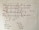
We have used LCD CFAF320240F-035T in our new product. The product has a user interface with the LCD module. The LCD interface used is SPI running at 14 MHz and the data and clock signals are sent from main baord to user interface board through a 1.2m shileded cable. Functionally the machine and the LCD works fine.
During one of the EMI/EMC test - Radiated Susceptibility (RS) EN61000-4-3, we had observed lot of LCD screen corruption. In this test the machine is subjected to a electromagnetic field of 10V/m in frequency range from 80 MHz to 1000 MHz in Anechoic Chamber. The screen corruption observed were - inverted image, wrong colors, white lines or completely white display. This corruption was also observed when there was no data being transferred from main board to LCD
Is the Crystalfontz LCD CFAF320240F-035T EMI/EMC compliant? Is there any test report available ? Is transferring of high speed SPI clock and data through 1.2 m shileded cable correct ?
Request your help or suggestions for resolving the issue.
Looking for additional LCD resources? Check out our LCD blog for the latest developments in LCD technology.