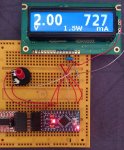
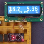
Interference shown when using a frame buffer in graphics mode

hennep

New member
CFAG14432C.jpg

I tried to use the CFAG14432C as a display for a power supply. The code that I used came from the CFAG14432_SPI_Arduino example from this site.
When I call the function 'Send_FrameBuffer_To_LCD', an interference is shown on the display. The display is kept in graphics mode all the time.
Is this a known behaviour? Can we stop output to the display somehow during the update or is there any other way to get rid of this distortion?
I've tried extra 100nF capacitors on the power supply input connector and between GND and the contrast pin. That didn't make any difference.

Code:
void Send_FrameBuffer_To_LCD( void ) {
    register uint8_t i;
    register uint8_t j;
    //
    //Setting to graphics mode commented out, display is kept in graphics mode all the time.
    //Commands were moved to the Arduino setup function
    //
    //write_command( 0x06 ); // entry mode -- cursor moves right, address counter increased by 1
    //write_command( 0x34 ); // extended function
    //write_command( 0x36 ); // graphic mode on
    //
    //Send the FrameBuffer RAM data to the LCD.
    for( j = 0; j < FRAME_HEIGHT_PIXELS; j++ ) {
        //Set Y address to this line, reset X address
        Set_Graphics_Mode_Address( 0, j );
        for( i = 0; i < FRAME_WIDTH_BYTES; i++ ) {
            write_data( framebuffer[j][i] );
        }
    }
}
Looking for additional LCD resources? Check out our LCD blog for the latest developments in LCD technology.
 
Last edited:

CF Kelsey

Administrator
Staff member
I'm not entirely sure what you mean by interference.

It should look essentially like this when the display is being updated -

Could you post some photos of the issue as well as of your whole set up so I can see the wiring etc?
 

hennep

New member
Hi Kelsey, thank you for your response and also thanks for moving the topic. I couldn't do that myself.
Maybe interference is not the right word. At least I do not expect it to be an electrical interference. The display is powered by 5V from the USB. In the mean time I have connected a 100uF electrolytic capacitor to the 5V between the microcontroller board and the LCD module. Also 470n to the contrast voltage and an extra 100n to the 5V, both directly to the connector strip.
I wanted to refresh the display every 100ms but I changed that to 3 times per second because the distortion was really annoying.
The display is stable without refreshing the frame. When this was a PC application I would use double buffering. That is why I asked if I could stop output to the display. Freezing the display during the update would solve this issue.
I could not find an overview of all possible commands, is such a list available? (found that: Sitronix ST7920)
In other forum topics I read about a DisplayOff/DisplayOn command. Does that freeze the output or does the display go dark completely? (goes dark)

A few photographs to show the set up.
IMG_20230526_092125.jpg

At the moment I am preparing a second display with shorter wiring. I know that development on a breadboard often adds unwanted electrical problems but I don't expect that to be the problem here because I did not see any faulty pixels in the display.

IMG_20230526_095435.jpg
R10 was moved to the R11 position to activate SPI instead of the default parallel bus.

IMG_20230526_095257.jpg
I wired the power for background light directly to the anode and cathode of the display because backlight was not connected to pins labeled as 14 and 15 of the connector strip. You can see the missing jumpers on the back of the pcb, photo with the black blob.

IMG_20230526_115822.jpg
Contrast was set using 3 SMD resistors directly on the connector pads. 2k2 and 5k6 parallel connected to 5V and 33k to GND. The red wire goes to the anode of the LED.

Less wiring but exactly the same distortion in the display. (I took the photo exactly during a rewrite)
IMG_20230526_120009.jpg
A link to a video to show the distortion in the display:
Setting FAST_SPI to 0 makes it even worse. The communication takes more time, so does the distortion:
 
Last edited:

hennep

New member
I've done some research in the weekend. I searched Github and tested a number of libraries and nearly all of them had the same problem. The only one that I have found that works correct is the U8G2 library from Oliver Kraus. U8G2 shows a stable display but I don't like its fonts though. For my application I had modified the Verdana Bold font, 22 pixels high with a different aspect ratio. I could not find many bold fonts with 22 pixels height in the U8G2 library, only some skinny ones.
So I continued work on my own code. I've sped up the algorithm by sending a burst of bytes per pixel line without the chip select for every byte. Below is a comparison between the relevant parts of the two Arduino sketches.
I am not completely satisfied with the result yet. It is a big improvement so far but not with a fully stable display yet. With a refresh rate of twice per second it will do for the moment. My Arduino sketch with the complete code is available at: https://github.com/HenniePeters/UIP-meter

At first I thought that the problem was caused by an electrical problem but the fact that U8G2 can produce a stable display means that it is a software problem after all. If one of your technicians has an idea how to tackle this, please let me know. I have the time to research it at the moment.
Some sources on the web say that after initialisation the reset pin of the ST7920 needs a 100ms LOW pulse. I hope that is not needed solve this as the reset pin is not available on this board.

Code from: Crystalfontz CFAG14432_SPI_Arduino.ino
Code:
//-----------------------------------------------------------------------------
void Send_FrameBuffer_To_LCD( void ) {
    register uint8_t    i;
    register uint8_t    j;
    write_command( 0x06 ); // entry mode -- cursor moves right, address counter increased by 1
    write_command( 0x34 ); // extended function
    write_command( 0x36 ); // graphic mode on

    //Send the FrameBuffer RAM data to the LCD.
    for( j = 0; j <= 31; j++ ) {
        //Set Y address to this line, reset X address
        Set_Graphics_Mode_Address( 0, j );
        for( i = 0; i <= 17; i++ ) {
            write_data( framebuffer[j][i] );
        }
    }
}
//-----------------------------------------------------------------------------
void Set_Graphics_Mode_Address( uint8_t x_word, uint8_t y ) {
    // Access extended functions register, graphics mode
    write_command( 0x34 );
    //Set Y pixel address
    write_command( 0x80 | y );
    //Set X byte address
    write_command( 0x80 | x_word );
    // Exit extended functions register, stay in graphics mode
    write_command( 0x36 );
}
//-----------------------------------------------------------------------------
void write_data( uint8_t data ) {
    //Select the chip, starting a 24-bit SPI transfer
#if FAST_SPI
    SET_SS;
#else
    digitalWrite( SPI_SS_PIN, HIGH );
#endif
    SPI_WriteByte( 0xFA ); // send data header
    SPI_WriteByte( data & 0xF0 ); // send high nibble
    SPI_WriteByte( ( data << 4 ) & 0xF0 ); // send low nibble
    //Release the chip, ending the SPI transfer
#if FAST_SPI
    CLR_SS;
#else
    digitalWrite( SPI_SS_PIN, LOW );
#endif
}
//-----------------------------------------------------------------------------
The modified code no longer needs the write_data function and "Set_Graphics_Mode_Address" was not changed.
Also going in and out graphics mode by "Send_FrameBuffer_To_LCD" is not necessary. Staying in graphics mode is more efficient.
Code:
//Checking FAST_SPI is no longer done in code, the check was moved to the header file. No speed change but better to read.
#if FAST_SPI
#define SET_SS  (PORTB |=  (SS_MASK))
#define CLR_SS  (PORTB &= ~(SS_MASK))
#else
#define SET_SS  digitalWrite( SPI_SS_PIN, HIGH );
#define CLR_SS  digitalWrite( SPI_SS_PIN, LOW );
#endif
//-----------------------------------------------------------------------------
void Send_FrameBuffer_To_LCD( void ) {
    register uint8_t i, j, b;
    // Reducing the number of redundant writes by not repeating 0xFA for every 
    // byte with write_data(). Doing that per pixel line instead. Also setting 
    // and clearing the chipselect for every byte slows down the algoritm.
    for( j = 0; j < FRAME_HEIGHT_PIXELS; j++ ) {
        Set_Graphics_Mode_Address( 0, j ); // Set Y address to line nr j, reset X address
        SET_SS;
        SPI_WriteByte( 0xFA ); // data
        for( i = 0; i < FRAME_WIDTH_BYTES; i++ ) {
            b = framebuffer[j][i];
            SPI_WriteByte( b & 0xF0 );  
            SPI_WriteByte( b << 4 );
        }
        CLR_SS;
    }
}
//-----------------------------------------------------------------------------
 

CF Kelsey

Administrator
Staff member
One option would be to use U8G2 and create a custom font file as described here: https://github.com/olikraus/u8g2/blob/c7dc077995ca513337a7d2a1970df693e18ee308/doc/faq.txt#L245

I believe what you're seeing is whether the background is drawn or not - https://github.com/olikraus/u8g2/wiki/u8g2reference#setfontmode

If you'd rather not use U8G2 and the issue is that you don't like how the characters overwrite each other visually on the display, I would suggest first sending a space character or dark rectangle to the place and then overwriting that with your desired character.
 
Top