Initially I tagged my problem at the end of another thread but I would like more input so I decided to start a new thread.
My problem is this;
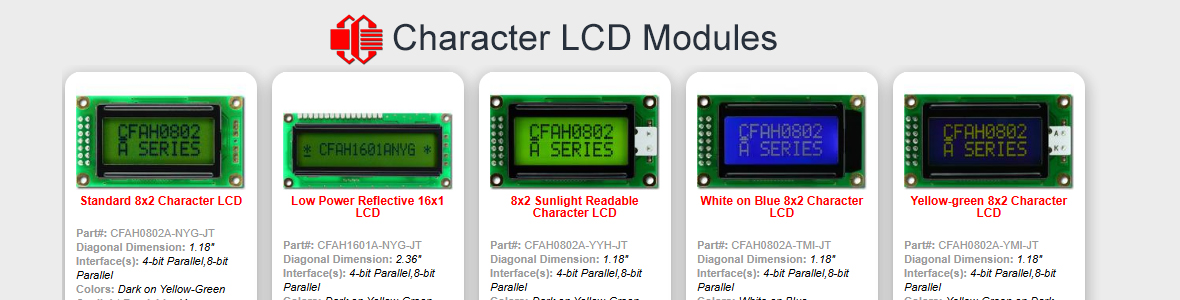
I have successfully interfaced my PIC16f676 to an Optrex DMC 50448N LCD using the built in LCD functions provided in PIC Basic Pro. I then found Crystalfontz's website and found their LCDs to be cheaper in volume then optrex so I decided to use them in my design. The problem is that when I got the Crystalfontz LCD CFAH0802-YYH-JP and dropped it into the circuit in place of the optrex it did not work. I thought that these type of LCDs, i.e. HD44780 or equivalent , were or should be interchangable. Is this not the case? Has anyone run into similiar issues and if so how were they resolved?
I am now trying to manually initialize the LCD and write data to it without using the builtin LCD functions. Here is my setup. I am using a 4-bit bus, the R/W line is hardwired low for write only, D7-D4 are wired to PORTC pins 3-0 respectively, enable is wired to PORTC bit 5, and RS bit is wired to PORTC bit 4. the PIC16f676 is a 14 pin chip and I have no spare I/O pins or any other pins for that matter available to change design it must work in this configuration or I will be forced back to Optrex LCDs.
I have spent several DAYS trying different combinations of the initalization sequence from the Cfontz datasheet to no avail. the closest I have come is to get the LCD initialized, I think!?, but cannot get characters to display. At the end of the initialization sequence I get either a cursor with a blinking square or a the last character before the square, a small o with two dots on top, in position one and then a cursor with a blinking square in position two. Then when I try to write data it looks like it wants to display but ll I get are squares appearing. Not only that but two at a time like it does not recognize that I am in 4-bit mode where it takes two writes to transfer the 8-bit character to the DDRAM. I am baffeled. Here is my code I am using to try this manual initialization and writing. I use very long pauses in there so I can see what the display looks like after each step. Any and all suggestions or comments are welcome.
TRISC = 0
'LCD INIT
PAUSE 2000
PORTC.4 = 0
PAUSEUS 1
PORTC.5 = 1
PAUSEUS 1
PORTC = %100011 'FIRST TIME
PAUSEUS 1
PORTC.5 = 0
PAUSE 100
PORTC.4 = 0
PAUSEUS 1
PORTC.5 = 1
PAUSEUS 1
PORTC = %100011 'SECOND TIME
PAUSEUS 1
PORTC.5 = 0
PAUSE 100
PORTC.4 = 0
PAUSEUS 1
PORTC.5 = 1
PAUSEUS 1
PORTC = %100011 'THIRD TIME
PAUSEUS 1
PORTC.5 = 0
PAUSE 1
PORTC.4 = 0
PAUSEUS 1
PORTC.5 = 1
PAUSEUS 1
PORTC = %100010 'FUNCTION SET (SET INTERFACE TO 4 BITS LONG)
PAUSEUS 1
PORTC.5 = 0
PAUSE 5000
PORTC.4 = 0
PAUSEUS 1
PORTC.5 = 1
PAUSEUS 1
PORTC = %100010 'FUNCTION SET (SET INTERFACE TO 4 BITS LONG)
PAUSEUS 1
PORTC.5 = 0
PAUSE 1
PORTC.4 = 0
PAUSEUS 1
PORTC.5 = 1
PAUSEUS 1
PORTC = %101000 'FUNCTION SET DISPLAY LINES = 2 FONT = 5X8
PAUSEUS 1
PORTC.5 = 0
PAUSE 1
PORTC.4 = 0
PAUSEUS 1
PORTC.5 = 1
PAUSEUS 1
PORTC = %100000 'DISPLAY ON
PAUSEUS 1
PORTC.5 = 0
PAUSE 1
PORTC.4 = 0
PAUSEUS 1
PORTC.5 = 1
PAUSEUS 1
PORTC = %101110
PAUSEUS 1
PORTC.5 = 0
PAUSE 1
PORTC.4 = 0
PAUSEUS 1
PORTC.5 = 1
PAUSEUS 1
PORTC = %100000 'DISPLAY CLEAR
PAUSEUS 1
PORTC.5 = 0
PAUSE 1
PORTC.4 = 0
PAUSEUS 1
PORTC.5 = 1
PAUSEUS 1
PORTC = %100001
PAUSEUS 1
PORTC.5 = 0
PAUSE 1
PORTC.4 = 0
PAUSEUS 1
PORTC.5 = 1
PAUSEUS 1
PORTC = %100000 'ENTRY MODE SET
PAUSEUS 1
PORTC.5 = 0
PAUSE 1
PORTC.4 = 0
PAUSEUS 1
PORTC.5 = 1
PAUSEUS 1
PORTC = %100110
PAUSEUS 1
PORTC.5 = 0
PAUSE 5000
PORTC.4 = 0
PAUSEUS 1
PORTC.5 = 1
PAUSEUS 1
PORTC = %100000 'CLEAR DISPLAY
PAUSEUS 1
PORTC.5 = 0
PAUSE 1
PORTC.4 = 0
PAUSEUS 1
PORTC.5 = 1
PAUSEUS 1
PORTC = %100001
PAUSEUS 1
PORTC.5 = 0
PAUSE 5000
'WRITE DATA TO DDRAM
MAIN:
PORTC.4 = 1
PAUSEUS 1
PORTC.5 = 1
PAUSEUS 1
PORTC = %110011 'SEND UPPER NIBBLE
PAUSEUS 1
PORTC.5 = 0
PAUSEUS 1
PORTC.5 = 1
PAUSEUS 1
PORTC = %110011 'SEND LOWER NIBBLE
PAUSEUS 1
PORTC.5 = 0
PAUSE 5000
GOTO MAIN
My problem is this;
I have successfully interfaced my PIC16f676 to an Optrex DMC 50448N LCD using the built in LCD functions provided in PIC Basic Pro. I then found Crystalfontz's website and found their LCDs to be cheaper in volume then optrex so I decided to use them in my design. The problem is that when I got the Crystalfontz LCD CFAH0802-YYH-JP and dropped it into the circuit in place of the optrex it did not work. I thought that these type of LCDs, i.e. HD44780 or equivalent , were or should be interchangable. Is this not the case? Has anyone run into similiar issues and if so how were they resolved?
I am now trying to manually initialize the LCD and write data to it without using the builtin LCD functions. Here is my setup. I am using a 4-bit bus, the R/W line is hardwired low for write only, D7-D4 are wired to PORTC pins 3-0 respectively, enable is wired to PORTC bit 5, and RS bit is wired to PORTC bit 4. the PIC16f676 is a 14 pin chip and I have no spare I/O pins or any other pins for that matter available to change design it must work in this configuration or I will be forced back to Optrex LCDs.
I have spent several DAYS trying different combinations of the initalization sequence from the Cfontz datasheet to no avail. the closest I have come is to get the LCD initialized, I think!?, but cannot get characters to display. At the end of the initialization sequence I get either a cursor with a blinking square or a the last character before the square, a small o with two dots on top, in position one and then a cursor with a blinking square in position two. Then when I try to write data it looks like it wants to display but ll I get are squares appearing. Not only that but two at a time like it does not recognize that I am in 4-bit mode where it takes two writes to transfer the 8-bit character to the DDRAM. I am baffeled. Here is my code I am using to try this manual initialization and writing. I use very long pauses in there so I can see what the display looks like after each step. Any and all suggestions or comments are welcome.
TRISC = 0
'LCD INIT
PAUSE 2000
PORTC.4 = 0
PAUSEUS 1
PORTC.5 = 1
PAUSEUS 1
PORTC = %100011 'FIRST TIME
PAUSEUS 1
PORTC.5 = 0
PAUSE 100
PORTC.4 = 0
PAUSEUS 1
PORTC.5 = 1
PAUSEUS 1
PORTC = %100011 'SECOND TIME
PAUSEUS 1
PORTC.5 = 0
PAUSE 100
PORTC.4 = 0
PAUSEUS 1
PORTC.5 = 1
PAUSEUS 1
PORTC = %100011 'THIRD TIME
PAUSEUS 1
PORTC.5 = 0
PAUSE 1
PORTC.4 = 0
PAUSEUS 1
PORTC.5 = 1
PAUSEUS 1
PORTC = %100010 'FUNCTION SET (SET INTERFACE TO 4 BITS LONG)
PAUSEUS 1
PORTC.5 = 0
PAUSE 5000
PORTC.4 = 0
PAUSEUS 1
PORTC.5 = 1
PAUSEUS 1
PORTC = %100010 'FUNCTION SET (SET INTERFACE TO 4 BITS LONG)
PAUSEUS 1
PORTC.5 = 0
PAUSE 1
PORTC.4 = 0
PAUSEUS 1
PORTC.5 = 1
PAUSEUS 1
PORTC = %101000 'FUNCTION SET DISPLAY LINES = 2 FONT = 5X8
PAUSEUS 1
PORTC.5 = 0
PAUSE 1
PORTC.4 = 0
PAUSEUS 1
PORTC.5 = 1
PAUSEUS 1
PORTC = %100000 'DISPLAY ON
PAUSEUS 1
PORTC.5 = 0
PAUSE 1
PORTC.4 = 0
PAUSEUS 1
PORTC.5 = 1
PAUSEUS 1
PORTC = %101110
PAUSEUS 1
PORTC.5 = 0
PAUSE 1
PORTC.4 = 0
PAUSEUS 1
PORTC.5 = 1
PAUSEUS 1
PORTC = %100000 'DISPLAY CLEAR
PAUSEUS 1
PORTC.5 = 0
PAUSE 1
PORTC.4 = 0
PAUSEUS 1
PORTC.5 = 1
PAUSEUS 1
PORTC = %100001
PAUSEUS 1
PORTC.5 = 0
PAUSE 1
PORTC.4 = 0
PAUSEUS 1
PORTC.5 = 1
PAUSEUS 1
PORTC = %100000 'ENTRY MODE SET
PAUSEUS 1
PORTC.5 = 0
PAUSE 1
PORTC.4 = 0
PAUSEUS 1
PORTC.5 = 1
PAUSEUS 1
PORTC = %100110
PAUSEUS 1
PORTC.5 = 0
PAUSE 5000
PORTC.4 = 0
PAUSEUS 1
PORTC.5 = 1
PAUSEUS 1
PORTC = %100000 'CLEAR DISPLAY
PAUSEUS 1
PORTC.5 = 0
PAUSE 1
PORTC.4 = 0
PAUSEUS 1
PORTC.5 = 1
PAUSEUS 1
PORTC = %100001
PAUSEUS 1
PORTC.5 = 0
PAUSE 5000
'WRITE DATA TO DDRAM
MAIN:
PORTC.4 = 1
PAUSEUS 1
PORTC.5 = 1
PAUSEUS 1
PORTC = %110011 'SEND UPPER NIBBLE
PAUSEUS 1
PORTC.5 = 0
PAUSEUS 1
PORTC.5 = 1
PAUSEUS 1
PORTC = %110011 'SEND LOWER NIBBLE
PAUSEUS 1
PORTC.5 = 0
PAUSE 5000
GOTO MAIN
Looking for additional LCD resources? Check out our LCD blog for the latest developments in LCD technology.