
Hi,
We have been having some problems initializing our display. We are interfacing to a dsPIC30F4011, programming in MPLAB with the C30 compiler. We are running in 8080 mode, with a 5V source. I have checked the Vo pin, and it is set to -18.8 V. I've double checked the wiring (according to the reference manual and the example given in the thread https://forum.crystalfontz.com/showthread.php?t=5025&highlight=CFAG320240CX) , followed the example code in both, and have come up with nothing.
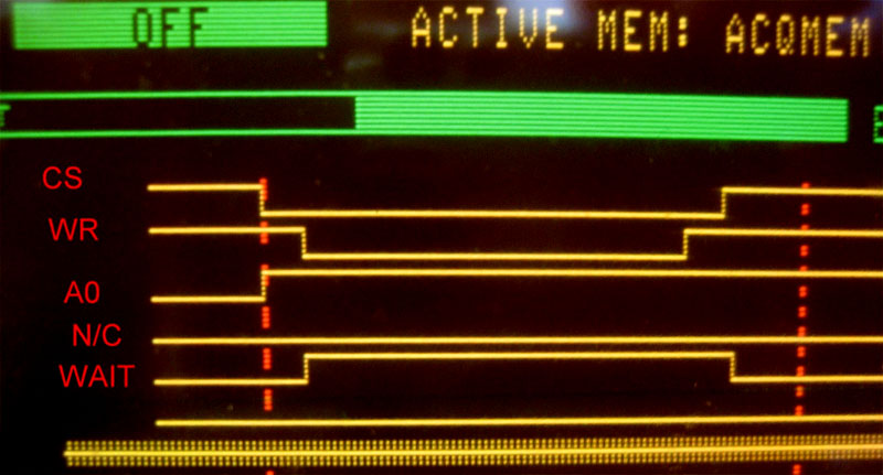
When we run our code (which I have attached), we get a purely black screen when we get to the "enable display" command. The lcd_init() function is the only thing called from a separate file. I've also attached a screenshot of some of our control lines in the process of sending a command to the LCD. As you can see, the WAIT line is very different than what the reference manual states it should be (it appears to be active HIGH), as well as going low after the CS line becomes inactive. We have tested our code with different delay times, but the WAIT line still goes to zero only after the CS line goes high. Do you know of any possible reasons for this?
Thanks for the help,
Derek
Simon Fraser University
We have been having some problems initializing our display. We are interfacing to a dsPIC30F4011, programming in MPLAB with the C30 compiler. We are running in 8080 mode, with a 5V source. I have checked the Vo pin, and it is set to -18.8 V. I've double checked the wiring (according to the reference manual and the example given in the thread https://forum.crystalfontz.com/showthread.php?t=5025&highlight=CFAG320240CX) , followed the example code in both, and have come up with nothing.
When we run our code (which I have attached), we get a purely black screen when we get to the "enable display" command. The lcd_init() function is the only thing called from a separate file. I've also attached a screenshot of some of our control lines in the process of sending a command to the LCD. As you can see, the WAIT line is very different than what the reference manual states it should be (it appears to be active HIGH), as well as going low after the CS line becomes inactive. We have tested our code with different delay times, but the WAIT line still goes to zero only after the CS line goes high. Do you know of any possible reasons for this?
Thanks for the help,
Derek
Simon Fraser University
Looking for additional LCD resources? Check out our LCD blog for the latest developments in LCD technology.
Attachments
-
 340.7 KB Views: 374
 -
1.4 KB Views: 439
-
 72.9 KB Views: 629