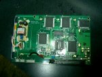
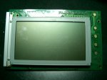
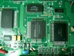
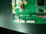
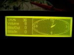
Have a new Mystery LCD Module

Freddy warbird

New member
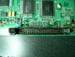
Here's a puzzle if someone wants to take a stab at it. This display "does" have an onboard controller, but after searching the web for a data sheet, I can't find anything. I don't know the manufacture other than the PCB manufacture.

Here's what I know:

PCB: PHICO D-0
0350 94V-0

Another # on the board is: P227-A1
CCFL backlit
Controller: EPSON S1D13305F00A1
Drivers: QTY 3 Sanyo's LC79401, and QTY 2 Sanyo's LC79430
Inverter: TDK CXA-L10A

It has an 40 pin IDC connector. Pins 1 through 5 appear to trace to SW0 to SW4. Pins 25 and 26 go to SW5 and SW6 traces. Pin 19 goes to the decade counter. Theres no dot, or marking on the decade counter to indicate where pin 1 is, but i'm guessing it's VDD. Heres the PDF on the decade counter. http://pdf1.alldatasheet.com/datasheet-pdf/view/255327/NXP/HEF4017BT.html Pin 21 and 22 go to a fairly wide trace that branches to too many directions to mention. Pin 34 is omitted. Pins 25 through 40 trace to P3 white six pin connector.

2 pin (P1) white connector traces to the inverter. Don't know which ones + & -, but that isn't too big a deal. It's probably 4.5 to 5V.

there is a 3 pin (P2) white connector, and a six pin (P3) white connector. The six pin (P3) white connector traces to the last six pins of the 40 pin IDC connector.

The screen frame size is 3" x 5"

Since this Display has an controller, i'm really interested in getting it figured out, so if anyone discovers anything, post whatever you know, or find out. Thanks.
Looking for additional LCD resources? Check out our LCD blog for the latest developments in LCD technology.
 

Attachments

Last edited:
Finding the Epson controller data sheet is a no brainer on Google.

Use an ohmmeter to find where the Epson signal pins RD, WR, CS, A0, D0-D7, Reset, Modesel0 & 1, Vdd, and Vss come out on the 40 pin header. Then hook it up to your favorite processor, and start experimenting with the instruction set in the data sheet. You might be able to find some sample code online.

You might have to experiment with the other connectors to turn on the backlight.
 

Freddy warbird

New member
Finding the Epson controller data sheet is a no brainer on Google.
Ya, I have no problem finding that, and already have it saved to my desktop.


Use an ohmmeter to find where the Epson signal pins RD, WR, CS, A0, D0-D7, Reset, Modesel0 & 1, Vdd, and Vss come out on the 40 pin header. Then hook it up to your favorite processor, and start experimenting with the instruction set in the data sheet. You might be able to find some sample code online.
EDIT: I rang out all the pins as noted except for what you call Modesel 0 & 1. I have no idea what that is. What pins are those?

RD= Receive Data pin 8 to pin 50
WR= write pin 9 to pin 51
CS= Chip Select pin 7 to pin 56
A0= Data Type Select 6 to pin 57
D0-D7= Data Bus pin 11 thru 17
Res= Reset pin 10 to pin 47
VDD= Volt + pin 19-20 to pin 58
VSS= Volts - pin 21-22-31-33 to pin 13
Inverter + = pin 27
Inverter - = pin 28

http://pdf1.alldatasheet.com/datasheet-pdf/view/230069/EPSON/S1D13305F00A.html


You might have to experiment with the other connectors to turn on the backlight.
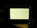
I just discovered it is not as simple as supplying 5v to the 2 pin white connector although its probably involved. That doesn't do nothing, and that mean theres more to it. However, there are VIN and GND test points directing on the TDK CXA-L10A inverter. I hit those with 5v, and the display lights up nice. It appears to be grey, or white background.
 

Attachments

Last edited:

Freddy warbird

New member
Well, I'm making some progress. I found the LCD Icon Editor for Windows 2000,however its only a demo. Cost money for a licence. I can use most of the software, just can't save any data. It is designed for the S1D13305f, and equivilants. There's also a presentation demo, but I don't know if it is only something to be view from the desktop, and not to the LCD module. I still haven't been able to get this thing running and display characters. I'm not sure I'm soldering the DB25 pins exactly right.


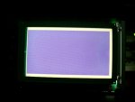
I managed to bring up all the pixels on the grid. They are purple, or violet in color, and the edges of the screen tend to get a little foggy after some time. I have a screen full of pixels.


I'm confident I have the DATA BUS right. D0-D7 On pins 2-9 of the DB25.

VSS GND pins 21-22-31-33 are all soldered between 18-25, and I have a BLK wire going to the Bread Board off of them to GND.

VDD pins 19-20 are going straight to 5V+ from the bread board.

Backlight is also wired to the Bread Board 5V+ to GND.

I'm concernd that these are wrong.

A0 is on pin 17 ?
CS is on GND ?
WR is on pin 14 ?
RD is on pin 16 ?

Now,
RD is an input, and I have it on an In/Out Control 2 register bit.
CS is also an Input, and I have it on GND. That's low all the time. That doens't seem right
AO is also an Input, and I have it on an In/Out.
WR is on Auto-linefeed.
I'm lost on Contrast control.

Anybody want to throw me a bone? :p

I hobby at my own risk, so don't worry about it.
 

Attachments

Freddy warbird

New member
Here's a little moive avi I took to show that the port does work with JdLCD running a program. Just chick the picture. The port works just nothing from this display yet. I don't believe JdLCD supports this display controller, but the port is working. Does anyone know if RAMTEX Icon editor (non licence) editor will display anything on an LCD Graphic display, or do you have to purchase it? It only says it won't save, but will it still display while running on the desktop?


Freddy warbird

New member
Well, I got this one working. $12.00 is all it cost. I'm Running Lcdstudio v2.1 on Windows 2000Pro x86 32bit. There are some bugs I need to work out, so other panel is on the back burner for the moment. This model has the Toshiba T6963c controller. The negative power generator I made has two ISL7660CPA's, and was key to powering up the drivers and see the contrast . The negative power generator is a cascading type I think, and has 4+ powering it form an adjustable 5v reg, and about -9v out, and about -7 volts though a 5k ohm pot sweeping the VO pin.


Question: If I simply touch the edge of the PCB, where the connector is, the image crashes to a blank screen. I cannot recover with reset, and must restart Lcdstudio. If I touch, or grab the display from the black frame, or anywhere else, I'm ok. :confused: Anyone know what could be the cause of this sensitivity?
 

Attachments

Last edited:

Freddy warbird

New member
I'd guess static charge from your body, or noise 60 Hz up thru RF, picked up by you as an antenna.
I've narrowed it down to one little spot between pin 1 and 6 on the edge of the board It acts just like pressing reset only the contrast usually doesn't come back, but sometimes it does. Even rubbing my mouse cord against that spot triggers it. Could static electricity run along the outside on the cord? I've tried running an additional ground from the board itself, but it still does it. even a piece of electrical tape covering the edge doesn't eliminate it. The Display will run for hours, but touch this spot, and crash. Other than that, this thing works great..
I can't see any metal in the laminate looking at it on edge.
CORRECTION: Yes, there are infact traces all the way to the edge of the board. Took a razor blade, cut and scraped them away. Now, I can touch the edge of the PCB and the crashing has stopped.
 
Last edited:
Top