Freddy warbird
New member
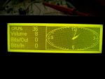
Here's a puzzle if someone wants to take a stab at it. This display "does" have an onboard controller, but after searching the web for a data sheet, I can't find anything. I don't know the manufacture other than the PCB manufacture.
Here's what I know:
PCB: PHICO D-0
0350 94V-0
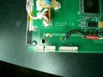
Another # on the board is: P227-A1
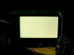
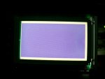
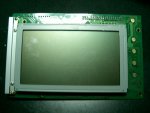
CCFL backlit
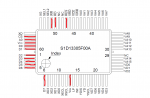
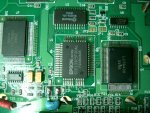
Controller: EPSON S1D13305F00A1
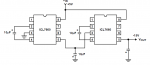
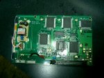
Drivers: QTY 3 Sanyo's LC79401, and QTY 2 Sanyo's LC79430
Inverter: TDK CXA-L10A
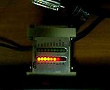
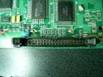
It has an 40 pin IDC connector. Pins 1 through 5 appear to trace to SW0 to SW4. Pins 25 and 26 go to SW5 and SW6 traces. Pin 19 goes to the decade counter. Theres no dot, or marking on the decade counter to indicate where pin 1 is, but i'm guessing it's VDD. Heres the PDF on the decade counter. http://pdf1.alldatasheet.com/datasheet-pdf/view/255327/NXP/HEF4017BT.html Pin 21 and 22 go to a fairly wide trace that branches to too many directions to mention. Pin 34 is omitted. Pins 25 through 40 trace to P3 white six pin connector.
2 pin (P1) white connector traces to the inverter. Don't know which ones + & -, but that isn't too big a deal. It's probably 4.5 to 5V.
there is a 3 pin (P2) white connector, and a six pin (P3) white connector. The six pin (P3) white connector traces to the last six pins of the 40 pin IDC connector.
The screen frame size is 3" x 5"
Since this Display has an controller, i'm really interested in getting it figured out, so if anyone discovers anything, post whatever you know, or find out. Thanks.
Here's what I know:
PCB: PHICO D-0
0350 94V-0
Another # on the board is: P227-A1
CCFL backlit
Controller: EPSON S1D13305F00A1
Drivers: QTY 3 Sanyo's LC79401, and QTY 2 Sanyo's LC79430
Inverter: TDK CXA-L10A
It has an 40 pin IDC connector. Pins 1 through 5 appear to trace to SW0 to SW4. Pins 25 and 26 go to SW5 and SW6 traces. Pin 19 goes to the decade counter. Theres no dot, or marking on the decade counter to indicate where pin 1 is, but i'm guessing it's VDD. Heres the PDF on the decade counter. http://pdf1.alldatasheet.com/datasheet-pdf/view/255327/NXP/HEF4017BT.html Pin 21 and 22 go to a fairly wide trace that branches to too many directions to mention. Pin 34 is omitted. Pins 25 through 40 trace to P3 white six pin connector.
2 pin (P1) white connector traces to the inverter. Don't know which ones + & -, but that isn't too big a deal. It's probably 4.5 to 5V.
there is a 3 pin (P2) white connector, and a six pin (P3) white connector. The six pin (P3) white connector traces to the last six pins of the 40 pin IDC connector.
The screen frame size is 3" x 5"
Since this Display has an controller, i'm really interested in getting it figured out, so if anyone discovers anything, post whatever you know, or find out. Thanks.
Looking for additional LCD resources? Check out our LCD blog for the latest developments in LCD technology.
Attachments
-
 CIMG2366.JPG176.2 KB · Views: 1,508
 -
 CIMG2367.JPG179.8 KB · Views: 1,156
 -
 CIMG2368.JPG181.5 KB · Views: 1,526
 -
 CIMG2369.JPG178.2 KB · Views: 998
 -
 CIMG2370.JPG180.6 KB · Views: 881
Last edited: