
CF Tech
Administrator
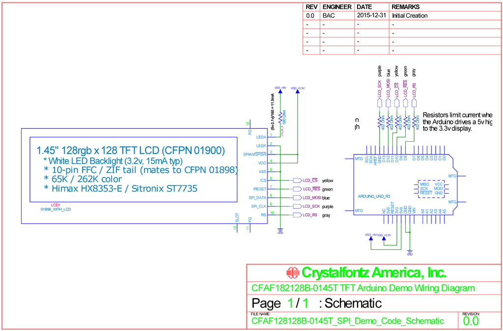
A customer asked for some help connecting the CFAF128128B-0145T 1.45" 12x128 full color TFT LCD. They wanted to have an example that only used software, so they could port it easily to their proprietary system.
I decided to use a SparkFun RedBoard that I had on my desk. I have also tested the code on a true-blue Arduino Uno R3, and it worked identically -- as you would expect.
To start, we need a plan -- in the form of a schematic (the full resolution PDF):
I used a small adapter board to break out the CFAF128128B-0145T 0.5mm FPC tail to 0.1" center pins, then used some WRJMPY40 to connect it up:
Update: kprice has uploaded a nice little ZIF breakout board at OSH Park that could be used here:
https://oshpark.com/shared_projects/PeXUHK4z

On back of the adapter board we added a 156 ohm dropping resistor for the white LED backlight, and jumped the spi mode line to high, selecting the 4-wire mode:

Connecting to the RedBoard/Arduino for power is straight-forward:

The LCD runs at 3.3v, but the RedBoard/Arduino runs at 5v so there is a problem with the voltage levels. One option is to use a level translator, but in this simple write-only example we can use current limiting resistors to protect the input on the LCD:

For the code, we made about the simplest sketch we could. This code stresses simplicity over speed. It can be used with the Arduino/RedBoard hardware SPI, or bit-banged software SPI:
CFAF128128B-0145T_SPI_Demo_Code.ino
Putting it all together:

And a video showing it in action:
https://www.youtube.com/watch?v=PXzmSylwjdY
I decided to use a SparkFun RedBoard that I had on my desk. I have also tested the code on a true-blue Arduino Uno R3, and it worked identically -- as you would expect.
To start, we need a plan -- in the form of a schematic (the full resolution PDF):
I used a small adapter board to break out the CFAF128128B-0145T 0.5mm FPC tail to 0.1" center pins, then used some WRJMPY40 to connect it up:
Update: kprice has uploaded a nice little ZIF breakout board at OSH Park that could be used here:
https://oshpark.com/shared_projects/PeXUHK4z
On back of the adapter board we added a 156 ohm dropping resistor for the white LED backlight, and jumped the spi mode line to high, selecting the 4-wire mode:
Connecting to the RedBoard/Arduino for power is straight-forward:
The LCD runs at 3.3v, but the RedBoard/Arduino runs at 5v so there is a problem with the voltage levels. One option is to use a level translator, but in this simple write-only example we can use current limiting resistors to protect the input on the LCD:
For the code, we made about the simplest sketch we could. This code stresses simplicity over speed. It can be used with the Arduino/RedBoard hardware SPI, or bit-banged software SPI:
CFAF128128B-0145T_SPI_Demo_Code.ino
Code:
//===========================================================================
//
// Code written for Arduino Uno R3
//
// CRYSTALFONTZ CFAF128128B-0145T 128X128 SPI COLOR 1.45" TFT
//
// Super-simple software bit-bang example code.
//
// ref: https://www.crystalfontz.com/product/cfaf128128b0145t
//
// 2015 - 12 - 31 Brent A. Crosby
//===========================================================================
//This is free and unencumbered software released into the public domain.
//
//Anyone is free to copy, modify, publish, use, compile, sell, or
//distribute this software, either in source code form or as a compiled
//binary, for any purpose, commercial or non-commercial, and by any
//means.
//
//In jurisdictions that recognize copyright laws, the author or authors
//of this software dedicate any and all copyright interest in the
//software to the public domain. We make this dedication for the benefit
//of the public at large and to the detriment of our heirs and
//successors. We intend this dedication to be an overt act of
//relinquishment in perpetuity of all present and future rights to this
//software under copyright law.
//
//THE SOFTWARE IS PROVIDED "AS IS", WITHOUT WARRANTY OF ANY KIND,
//EXPRESS OR IMPLIED, INCLUDING BUT NOT LIMITED TO THE WARRANTIES OF
//MERCHANTABILITY, FITNESS FOR A PARTICULAR PURPOSE AND NONINFRINGEMENT.
//IN NO EVENT SHALL THE AUTHORS BE LIABLE FOR ANY CLAIM, DAMAGES OR
//OTHER LIABILITY, WHETHER IN AN ACTION OF CONTRACT, TORT OR OTHERWISE,
//ARISING FROM, OUT OF OR IN CONNECTION WITH THE SOFTWARE OR THE USE OR
//OTHER DEALINGS IN THE SOFTWARE.
//
//For more information, please refer to <http://unlicense.org/>
//============================================================================
//
// Display is Crystalfontz CFAF128128B-0145T
// https://www.crystalfontz.com/product/cfaf128128b0145t
//
// The controller is a Sitronix ST7735S
// http://www.crystalfontz.com/controllers/Sitronix/ST7735S/
//
//============================================================================
#define HARDWARE_SPI 0
#include <avr/io.h>
#if(HARDWARE_SPI)
// C:\Program Files (x86)\Arduino\hardware\arduino\avr\libraries\SPI\SPI.cpp
// C:\Program Files (x86)\Arduino\hardware\arduino\avr\libraries\SPI\SPI.h
#include <SPI.h>
#endif
#include <util/delay.h>
#include <avr/pgmspace.h>
// This is supposed to be set somewhere in the AVR Studio, but I can't find
// the place :( In any case, our dev board, an Arduino UNO R3 runs at 16MHz,
// and this define makes the delays come out correctly.
# define F_CPU 16000000UL
//============================================================================
//
// LCD SPI & control lines
// ARD | Port | LCD
// --------+------+-------------------------
// #8/D8 | PB0 | LCD_RS
// #9/D9 | PB1 | LCD_RESET
// #10/D10 | PB2 | LCD_CS_NOT (or SPI SS)
// #11/D11 | PB3 | LCD_MOSI (hardware SPI)
// #12/D12 | PB4 | not used (would be MISO)
// #13/D13 | PB5 | LCD_SCK (hardware SPI)
#define CLR_RS (PORTB &= ~(0x01))
#define SET_RS (PORTB |= (0x01))
#define CLR_RESET (PORTB &= ~(0x02))
#define SET_RESET (PORTB |= (0x02))
#define CLR_CS (PORTB &= ~(0x04))
#define SET_CS (PORTB |= (0x04))
#define CLR_MOSI (PORTB &= ~(0x08))
#define SET_MOSI (PORTB |= (0x08))
#define CLR_SCK (PORTB &= ~(0x20))
#define SET_SCK (PORTB |= (0x20))
//============================================================================
void SPI_Bit_Bang_Transfer(uint8_t data)
{
//Push each of the 8 data bits out.
for(uint8_t mask=0x80;mask;mask>>=1)
{
//Set the MOSI pin high or low depending on if our mask
//corresponds to a 1 or 0 in the data.
if(mask&data)
{
SET_MOSI;
}
else
{
CLR_MOSI;
}
//Clock it in.
SET_SCK;
CLR_SCK;
}
}
//============================================================================
void SPI_sendCommand(uint8_t command)
{
// Select the LCD's command register
CLR_RS;
// Select the LCD controller
CLR_CS;
//Send the command via SPI:
#if(HARDWARE_SPI)
SPI.transfer(command);
#else
SPI_Bit_Bang_Transfer(command);
#endif
// Deselect the LCD controller
CLR_CS;
}
//----------------------------------------------------------------------------
void SPI_sendData(uint8_t data)
{
// Select the LCD's data register
SET_RS;
// Select the LCD controller
CLR_CS;
//Send the command via SPI:
#if(HARDWARE_SPI)
SPI.transfer(data);
#else
SPI_Bit_Bang_Transfer(data);
#endif
// Deselect the LCD controller
CLR_CS;
}
//----------------------------------------------------------------------------
// Defines for the ST7735 registers.
// ref: https://www.crystalfontz.com/products/document/3277/ST7735_V2.1_20100505.pdf
#define ST7735_SLPOUT (0x11)
#define ST7735_DISPON (0x29)
#define ST7735_CASET (0x2A)
#define ST7735_RASET (0x2B)
#define ST7735_RAMWR (0x2C)
#define ST7735_RAMRD (0x2E)
#define ST7735_MADCTL (0x36)
#define ST7735_COLMOD (0x3A)
#define ST7735_FRMCTR1 (0xB1)
#define ST7735_FRMCTR2 (0xB2)
#define ST7735_FRMCTR3 (0xB3)
#define ST7735_INVCTR (0xB4)
#define ST7735_PWCTR1 (0xC0)
#define ST7735_PWCTR2 (0xC1)
#define ST7735_PWCTR3 (0xC2)
#define ST7735_PWCTR4 (0xC3)
#define ST7735_PWCTR5 (0xC4)
#define ST7735_VMCTR1 (0xC5)
#define ST7735_GAMCTRP1 (0xE0)
#define ST7735_GAMCTRN1 (0xE1)
//----------------------------------------------------------------------------
void Initialize_LCD(void)
{
//Reset the LCD controller
CLR_RESET;
delay(1);//10µS min
SET_RESET;
delay(150);//120mS max
//SLPOUT (11h): Sleep Out ("Sleep Out" is chingrish for "wake")
//The DC/DC converter is enabled, Internal display oscillator
//is started, and panel scanning is started.
SPI_sendCommand(ST7735_SLPOUT);
delay(120);
//FRMCTR1 (B1h): Frame Rate Control (In normal mode/ Full colors)
//Set the frame frequency of the full colors normal mode.
// * Frame rate=fosc/((RTNA + 20) x (LINE + FPA + BPA))
// * 1 < FPA(front porch) + BPA(back porch) ; Back porch ?0
//Note: fosc = 333kHz
SPI_sendCommand(ST7735_FRMCTR1);//In normal mode(Full colors)
SPI_sendData(0x02);//RTNB: set 1-line period
SPI_sendData(0x35);//FPB: front porch
SPI_sendData(0x36);//BPB: back porch
//FRMCTR2 (B2h): Frame Rate Control (In Idle mode/ 8-colors)
//Set the frame frequency of the Idle mode.
// * Frame rate=fosc/((RTNB + 20) x (LINE + FPB + BPB))
// * 1 < FPB(front porch) + BPB(back porch) ; Back porch ?0
//Note: fosc = 333kHz
SPI_sendCommand(ST7735_FRMCTR2);//In Idle mode (8-colors)
SPI_sendData(0x02);//RTNB: set 1-line period
SPI_sendData(0x35);//FPB: front porch
SPI_sendData(0x36);//BPB: back porch
//FRMCTR3 (B3h): Frame Rate Control (In Partial mode/ full colors)
//Set the frame frequency of the Partial mode/ full colors.
// * 1st parameter to 3rd parameter are used in line inversion mode.
// * 4th parameter to 6th parameter are used in frame inversion mode.
// * Frame rate=fosc/((RTNC + 20) x (LINE + FPC + BPC))
// * 1 < FPC(front porch) + BPC(back porch) ; Back porch ?0
//Note: fosc = 333kHz
SPI_sendCommand(ST7735_FRMCTR3);//In partial mode + Full colors
SPI_sendData(0x02);//RTNC: set 1-line period
SPI_sendData(0x35);//FPC: front porch
SPI_sendData(0x36);//BPC: back porch
SPI_sendData(0x02);//RTND: set 1-line period
SPI_sendData(0x35);//FPD: front porch
SPI_sendData(0x36);//BPD: back porch
//INVCTR (B4h): Display Inversion Control
SPI_sendCommand(ST7735_INVCTR);
SPI_sendData(0x07);
// 0000 0ABC
// |||| ||||-- NLC: Inversion setting in full Colors partial mode
// |||| ||| (0=Line Inversion, 1 = Frame Inversion)
// |||| |||--- NLB: Inversion setting in idle mode
// |||| || (0=Line Inversion, 1 = Frame Inversion)
// |||| ||---- NLA: Inversion setting in full Colors normal mode
// |||| |----- Unused: 0
//PWCTR1 (C0h): Power Control 1
SPI_sendCommand(ST7735_PWCTR1);
SPI_sendData(0x02);// VRH[4:0] (0-31) Sets GVDD
// VRH=0x00 => GVDD=5.0v
// VRH=0x1F => GVDD=3.0v
// Each tick is a variable step:
// VRH[4:0] | VRH | GVDD
// 00000b | 0x00 | 5.00v
// 00001b | 0x01 | 4.75v
// 00010b | 0x02 | 4.70v <<<<<
// 00011b | 0x03 | 4.65v
// 00100b | 0x04 | 4.60v
// 00101b | 0x05 | 4.55v
// 00110b | 0x06 | 4.50v
// 00111b | 0x07 | 4.45v
// 01000b | 0x08 | 4.40v
// 01001b | 0x09 | 4.35v
// 01010b | 0x0A | 4.30v
// 01011b | 0x0B | 4.25v
// 01100b | 0x0C | 4.20v
// 01101b | 0x0D | 4.15v
// 01110b | 0x0E | 4.10v
// 01111b | 0x0F | 4.05v
// 10000b | 0x10 | 4.00v
// 10001b | 0x11 | 3.95v
// 10010b | 0x12 | 3.90v
// 10011b | 0x13 | 3.85v
// 10100b | 0x14 | 3.80v
// 10101b | 0x15 | 3.75v
// 10110b | 0x16 | 3.70v
// 10111b | 0x17 | 3.65v
// 11000b | 0x18 | 3.60v
// 11001b | 0x19 | 3.55v
// 11010b | 0x1A | 3.50v
// 11011b | 0x1B | 3.45v
// 11100b | 0x1C | 3.40v
// 11101b | 0x1D | 3.35v
// 11110b | 0x1E | 3.25v
// 11111b | 0x1F | 3.00v
SPI_sendData(0x02);// 010i i000
// |||| ||||-- Unused: 0
// |||| |----- IB_SEL0:
// ||||------- IB_SEL1:
// |||-------- Unused: 010
// IB_SEL[1:0] | IB_SEL | AVDD
// 00b | 0x00 | 2.5µA <<<<<
// 01b | 0x01 | 2.0µA
// 10b | 0x02 | 1.5µA
// 11b | 0x03 | 1.0µA
//PWCTR2 (C1h): Power Control 2
// * Set the VGH and VGL supply power level
//Restriction: VGH-VGL <= 32V
SPI_sendCommand(ST7735_PWCTR2);
SPI_sendData(0xC5);// BT[2:0] (0-15) Sets GVDD
// BT[2:0] | VGH | VGL
// 000b | 4X | 9.80v | -3X | -7.35v
// 001b | 4X | 9.80v | -4X | -9.80v
// 010b | 5X | 12.25v | -3X | -7.35v
// 011b | 5X | 12.25v | -4X | -9.80v
// 100b | 5X | 12.25v | -5X | -12.25v
// 101b | 6X | 14.70v | -3X | -7.35v <<<<<
// 110b | 6X | 14.70v | -4X | -9.80v
// 111b | 6X | 14.70v | -5X | -12.25v
//PWCTR3 (C2h): Power Control 3 (in Normal mode/ Full colors)
// * Set the amount of current in Operational amplifier in
// normal mode/full colors.
// * Adjust the amount of fixed current from the fixed current
// source in the operational amplifier for the source driver.
// * Set the Booster circuit Step-up cycle in Normal mode/ full
// colors.
SPI_sendCommand(ST7735_PWCTR3);
SPI_sendData(0x0D);// AP[2:0] Sets Operational Amplifier Bias Current
// AP[2:0] | Function
// 000b | Off
// 001b | Small
// 010b | Medium Low
// 011b | Medium
// 100b | Medium High
// 101b | Large <<<<<
// 110b | reserved
// 111b | reserved
SPI_sendData(0x00);// DC[2:0] Booster Frequency
// DC[2:0] | Circuit 1 | Circuit 2,4
// 000b | BCLK / 1 | BCLK / 1 <<<<<
// 001b | BCLK / 1 | BCLK / 2
// 010b | BCLK / 1 | BCLK / 4
// 011b | BCLK / 2 | BCLK / 2
// 100b | BCLK / 2 | BCLK / 4
// 101b | BCLK / 4 | BCLK / 4
// 110b | BCLK / 4 | BCLK / 8
// 111b | BCLK / 4 | BCLK / 16
//PWCTR4 (C3h): Power Control 4 (in Idle mode/ 8-colors)
// * Set the amount of current in Operational amplifier in
// normal mode/full colors.
// * Adjust the amount of fixed current from the fixed current
// source in the operational amplifier for the source driver.
// * Set the Booster circuit Step-up cycle in Normal mode/ full
// colors.
SPI_sendCommand(ST7735_PWCTR4);
SPI_sendData(0x8D);// AP[2:0] Sets Operational Amplifier Bias Current
// AP[2:0] | Function
// 000b | Off
// 001b | Small
// 010b | Medium Low
// 011b | Medium
// 100b | Medium High
// 101b | Large <<<<<
// 110b | reserved
// 111b | reserved
SPI_sendData(0x1A);// DC[2:0] Booster Frequency
// DC[2:0] | Circuit 1 | Circuit 2,4
// 000b | BCLK / 1 | BCLK / 1
// 001b | BCLK / 1 | BCLK / 2
// 010b | BCLK / 1 | BCLK / 4 <<<<<
// 011b | BCLK / 2 | BCLK / 2
// 100b | BCLK / 2 | BCLK / 4
// 101b | BCLK / 4 | BCLK / 4
// 110b | BCLK / 4 | BCLK / 8
// 111b | BCLK / 4 | BCLK / 16
//PPWCTR5 (C4h): Power Control 5 (in Partial mode/ full-colors)
// * Set the amount of current in Operational amplifier in
// normal mode/full colors.
// * Adjust the amount of fixed current from the fixed current
// source in the operational amplifier for the source driver.
// * Set the Booster circuit Step-up cycle in Normal mode/ full
// colors.
SPI_sendCommand(ST7735_PWCTR5);
SPI_sendData(0x8D);// AP[2:0] Sets Operational Amplifier Bias Current
// AP[2:0] | Function
// 000b | Off
// 001b | Small
// 010b | Medium Low
// 011b | Medium
// 100b | Medium High
// 101b | Large <<<<<
// 110b | reserved
// 111b | reserved
SPI_sendData(0xEE);// DC[2:0] Booster Frequency
// DC[2:0] | Circuit 1 | Circuit 2,4
// 000b | BCLK / 1 | BCLK / 1
// 001b | BCLK / 1 | BCLK / 2
// 010b | BCLK / 1 | BCLK / 4
// 011b | BCLK / 2 | BCLK / 2
// 100b | BCLK / 2 | BCLK / 4
// 101b | BCLK / 4 | BCLK / 4
// 110b | BCLK / 4 | BCLK / 8 <<<<<
// 111b | BCLK / 4 | BCLK / 16
//VMCTR1 (C5h): VCOM Control 1
SPI_sendCommand(ST7735_VMCTR1);
SPI_sendData(0x51);// Default: 0x51 => +4.525
// VMH[6:0] (0-100) Sets VCOMH
// VMH=0x00 => VCOMH= +2.5v
// VMH=0x64 => VCOMH= +5.0v
SPI_sendData(0x4D);// Default: 0x4D => -0.575
// VML[6:0] (4-100) Sets VCOML
// VML=0x04 => VCOML= -2.4v
// VML=0x64 => VCOML= 0.0v
//GMCTRP1 (E0h): Gamma ‘+’polarity Correction Characteristics Setting
SPI_sendCommand(ST7735_GAMCTRP1);
SPI_sendData(0x0a);
SPI_sendData(0x1c);
SPI_sendData(0x0c);
SPI_sendData(0x14);
SPI_sendData(0x33);
SPI_sendData(0x2b);
SPI_sendData(0x24);
SPI_sendData(0x28);
SPI_sendData(0x27);
SPI_sendData(0x25);
SPI_sendData(0x2C);
SPI_sendData(0x39);
SPI_sendData(0x00);
SPI_sendData(0x05);
SPI_sendData(0x03);
SPI_sendData(0x0d);
//GMCTRN1 (E1h): Gamma ‘-’polarity Correction Characteristics Setting
SPI_sendCommand(ST7735_GAMCTRN1);
SPI_sendData(0x0a);
SPI_sendData(0x1c);
SPI_sendData(0x0c);
SPI_sendData(0x14);
SPI_sendData(0x33);
SPI_sendData(0x2b);
SPI_sendData(0x24);
SPI_sendData(0x28);
SPI_sendData(0x27);
SPI_sendData(0x25);
SPI_sendData(0x2D);
SPI_sendData(0x3a);
SPI_sendData(0x00);
SPI_sendData(0x05);
SPI_sendData(0x03);
SPI_sendData(0x0d);
//COLMOD (3Ah): Interface Pixel Format
// * This command is used to define the format of RGB picture
// data, which is to be transferred via the MCU interface.
SPI_sendCommand(ST7735_COLMOD);
SPI_sendData(0x06);// Default: 0x06 => 18-bit/pixel
// IFPF[2:0] MCU Interface Color Format
// IFPF[2:0] | Format
// 000b | reserved
// 001b | reserved
// 010b | reserved
// 011b | 12-bit/pixel
// 100b | reserved
// 101b | 16-bit/pixel
// 110b | 18-bit/pixel <<<<<
// 111b | reserved
//DISPON (29h): Display On
// * This command is used to recover from DISPLAY OFF mode. Output
// from the Frame Memory is enabled.
// * This command makes no change of contents of frame memory.
// * This command does not change any other status.
// * The delay time between DISPON and DISPOFF needs 120ms at least
SPI_sendCommand(ST7735_DISPON);//Display On
delay(1);
//MADCTL (36h): Memory Data Access Control
SPI_sendCommand(ST7735_MADCTL);
SPI_sendData(0x40);// YXVL RH--
// |||| ||||-- Unused: 0
// |||| ||---- MH: Horizontal Refresh Order
// |||| | 0 = left to right
// |||| | 1 = right to left
// |||| |----- RGB: RGB vs BGR Order
// |||| 0 = RGB color filter panel
// |||| 1 = BGR color filter panel
// ||||------- ML: Vertical Refresh Order
// ||| 0 = top to bottom
// ||| 1 = bottom to top
// |||-------- MV: Row / Column Exchange
// ||--------- MX: Column Address Order <<<<<
// |---------- MY: Row Address Order
}
//============================================================================
void Set_LCD_for_write_at_X_Y(uint8_t x, uint8_t y)
{
//CASET (2Ah): Column Address Set
// * The value of XS [15:0] and XE [15:0] are referred when RAMWR
// command comes.
// * Each value represents one column line in the Frame Memory.
// * XS [15:0] always must be equal to or less than XE [15:0]
SPI_sendCommand(ST7735_CASET); //Column address set
//Write the parameters for the "column address set" command
SPI_sendData(0x00); //Start MSB = XS[15:8]
SPI_sendData(0x02 + x); //Start LSB = XS[ 7:0]
SPI_sendData(0x00); //End MSB = XE[15:8]
SPI_sendData(0x81); //End LSB = XE[ 7:0]
//Write the "row address set" command to the LCD
//RASET (2Bh): Row Address Set
// * The value of YS [15:0] and YE [15:0] are referred when RAMWR
// command comes.
// * Each value represents one row line in the Frame Memory.
// * YS [15:0] always must be equal to or less than YE [15:0]
SPI_sendCommand(ST7735_RASET); //Row address set
//Write the parameters for the "row address set" command
SPI_sendData(0x00); //Start MSB = YS[15:8]
SPI_sendData(0x01 + y); //Start LSB = YS[ 7:0]
SPI_sendData(0x00); //End MSB = YE[15:8]
SPI_sendData(0x80); //End LSB = YE[ 7:0]
//Write the "write data" command to the LCD
//RAMWR (2Ch): Memory Write
SPI_sendCommand(ST7735_RAMWR); //write data
}
//============================================================================
void Fill_LCD(uint8_t R, uint8_t G, uint8_t B)
{
register int
i;
Set_LCD_for_write_at_X_Y(0, 0);
//Fill display with a given RGB value
for (i = 0; i < (128 * 128); i++)
{
SPI_sendData(B); //Blue
SPI_sendData(G); //Green
SPI_sendData(R); //Red
}
}
//============================================================================
void Put_Pixel(uint8_t x, uint8_t y, uint8_t R, uint8_t G, uint8_t B)
{
Set_LCD_for_write_at_X_Y(x, y);
//Write the single pixel's worth of data
SPI_sendData(B); //Blue
SPI_sendData(G); //Green
SPI_sendData(R); //Red
}
//============================================================================
// From: http://en.wikipedia.org/wiki/Midpoint_circle_algorithm
void LCD_Circle(uint8_t x0, uint8_t y0, uint8_t radius, uint8_t R, uint8_t G, uint8_t B)
{
uint8_t x = radius;
uint8_t y = 0;
int16_t radiusError = 1 - (int16_t) x;
while (x >= y)
{
//11 O'Clock
Put_Pixel(x0 - y, y0 + x, R, G, B);
//1 O'Clock
Put_Pixel(x0 + y, y0 + x, R, G, B);
//10 O'Clock
Put_Pixel(x0 - x, y0 + y, R, G, B);
//2 O'Clock
Put_Pixel(x0 + x, y0 + y, R, G, B);
//8 O'Clock
Put_Pixel(x0 - x, y0 - y, R, G, B);
//4 O'Clock
Put_Pixel(x0 + x, y0 - y, R, G, B);
//7 O'Clock
Put_Pixel(x0 - y, y0 - x, R, G, B);
//5 O'Clock
Put_Pixel(x0 + y, y0 - x, R, G, B);
y++;
if (radiusError < 0)
radiusError += (int16_t)(2 * y + 1);
else
{
x--;
radiusError += 2 * (((int16_t) y - (int16_t) x) + 1);
}
}
}
//============================================================================
void setup()
{
// LCD SPI & control lines
// ARD | Port | LCD
// --------+------+-------------------------
// #8/D8 | PB0 | LCD_RS
// #9/D9 | PB1 | LCD_RESET
// #10/D10 | PB2 | LCD_CS_NOT (or SPI SS)
// #11/D11 | PB3 | LCD_MOSI (hardware SPI)
// #12/D12 | PB4 | not used (would be MISO)
// #13/D13 | PB5 | LCD_SCK (hardware SPI)
DDRB |= 0x2F;
//Drive the ports to a reasonable starting state.
CLR_RESET;
CLR_RS;
SET_CS;
CLR_MOSI;
CLR_SCK;
#if(HARDWARE_SPI)
// initialize SPI. By default the clock is 4MHz. The chip is good to 10 MHz
SPI.begin();
//Bump the clock to 8MHz. Appears to be the maximum.
SPI.beginTransaction(SPISettings(8000000, MSBFIRST, SPI_MODE0));
#endif
}
//============================================================================
void loop()
{
uint8_t
i;
uint8_t
j;
uint8_t
x;
uint8_t
sub_x;
uint8_t
y;
uint8_t
sub_y;
//Initialize the LCD controller
Initialize_LCD();
//Fill display with a given RGB value
Fill_LCD(0x00,0x00,0xFF);
//Draw a cyan circle
LCD_Circle(64, 64, 63,0x00,0xFF,0xFF);
//Draw a green circle
LCD_Circle(21, 64, 20,0x00,0xFF,0x00);
//Draw a white circle
LCD_Circle(64, 64, 20,0xFF,0xFF,0xFF);
//Draw a red circle
LCD_Circle(107, 64, 20,0xFF,0x00,0x00);
//Draw a purple circle
LCD_Circle(64, 107, 16,0xFF,0x00,0xFF);
//Draw a orange circle
LCD_Circle(64, 21, 14,0xFF,0xA5,0x00);
delay(1000);
Fill_LCD(0x00,0x00,0x00);
for(i=2;i<60;i+=2)
{
LCD_Circle(i+2, 64, i,i<<2,0xff-(i<<2),0x00);
}
delay(1000);
//Write a 8x8 checkerboard
for(x=0;x<=15;x++)
{
for(y=0;y<=15;y++)
{
for(sub_x=0;sub_x<=7;sub_x++)
for(sub_y=0;sub_y<=7;sub_y++)
if(((x&0x01)&&!(y&0x01)) || (!(x&0x01)&&(y&0x01)))
Put_Pixel((x<<3)+sub_x,(y<<3)+sub_y, 0x00, 0x00, 0x00);
else
Put_Pixel((x<<3)+sub_x,(y<<3)+sub_y, 0xFF, 0xFF-(x<<4), 0xFF-(y<<4));
}
}
delay(1000);
} // void loop()
//============================================================================And a video showing it in action:
https://www.youtube.com/watch?v=PXzmSylwjdY
Looking for additional LCD resources? Check out our LCD blog for the latest developments in LCD technology.
Last edited:
