
CF Tech
Administrator
I was recently tasked with powering up our new 16X2 Character OLED Modules:

These modules are pretty nice. They are the same size as our CFAH1602C series 16x2 Character LCD modules, and thinner as a bonus. The OLED's contrast is fantastic, and they have a crisp look that is hard to beat.
Another nice thing is that they have 4 software-selectable character sets, so you won't be stuck wanting for the omega or mu symbol.
Since I had an Arduino Uno handy, I decided to port the SPI version of the AVR code for this OLED to the Arduino. Here are all the parts you will need:

You will need to order your CFAL1602C pre-confgured for SPI, or follow the instructions in the CFAL1602C datasheet to make the conversion:

Once that is done, use some of the jumper wires to connect to the pins used for SPI on the CFAL1602C :

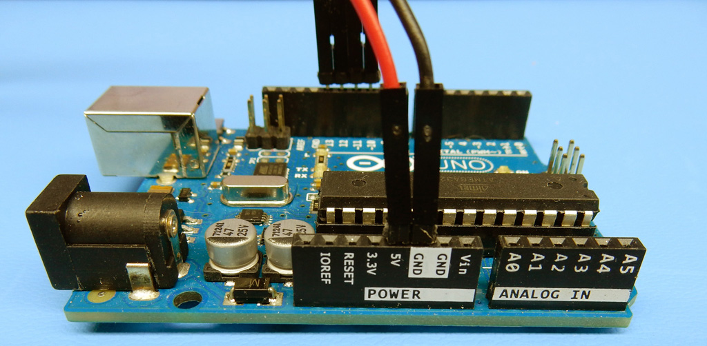
Then connect the 5v power and ground pins to the Arduino:
And complete the connections of the OLED's SPI pins to the Arduino:

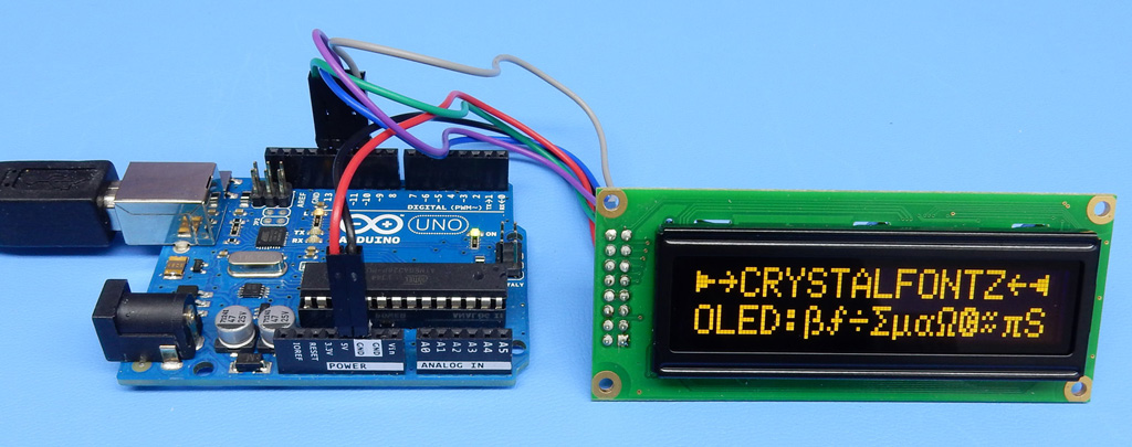
You then just need to connect the Arduino to your PC and open the sketch CFAL1602C_SPI_Arduino.ino. Upload and you will be rewarded with OLED goodness:
About the code
The SPI is done in software, since the WS0010 OLED controller requires a 10-bit SPI transfer. Here is an implementation of "proper Arduino" code for the 10-bit SPI:
This code transfers at a clock frequency of about ~57KHz, and it takes about ~180uS, to complete one 10-bit write, you won't die from old age waiting for it:

But the old assembly-coding EE in me wanted to see if it could go a little faster
 . Starting with some optimized Arduino Software SPI examples, I was able to do a bit better:
That speeds up things by a factor of 47 times, bringing a transfer from 180uS to 3.8us. The equivalent clock frequency from 247KHz to 2.6MHz. Very nice:

Of course either routine will work . . . the "proper Arduino" should be more portable.
Have fun connecting an OLED to your Arduino, feel free post your pictures or questions.
These modules are pretty nice. They are the same size as our CFAH1602C series 16x2 Character LCD modules, and thinner as a bonus. The OLED's contrast is fantastic, and they have a crisp look that is hard to beat.
Another nice thing is that they have 4 software-selectable character sets, so you won't be stuck wanting for the omega or mu symbol.
Since I had an Arduino Uno handy, I decided to port the SPI version of the AVR code for this OLED to the Arduino. Here are all the parts you will need:
- Crystalfontz CFAL1602C OLED in your preferred color
- Connection wires. I used some standard 0.1" headers I had around, and a pack of WRJMPY40 jumper wires
- An Arduino Uno R3
You will need to order your CFAL1602C pre-confgured for SPI, or follow the instructions in the CFAL1602C datasheet to make the conversion:
Once that is done, use some of the jumper wires to connect to the pins used for SPI on the CFAL1602C :
Then connect the 5v power and ground pins to the Arduino:
And complete the connections of the OLED's SPI pins to the Arduino:
- SS: Slave Select
- MOSI: Master (Arduino) Out, Slave (OLED) In
- MISO: Master (Arduino) In, Slave (OLED) Out
- SCK: Spi ClocK
You then just need to connect the Arduino to your PC and open the sketch CFAL1602C_SPI_Arduino.ino. Upload and you will be rewarded with OLED goodness:
About the code
The SPI is done in software, since the WS0010 OLED controller requires a 10-bit SPI transfer. Here is an implementation of "proper Arduino" code for the 10-bit SPI:
Code:
  //Straight-forward software SPI 10-bit transfer code, perhaps
  //easier to understand, possibly more portable. Certainly slower.
  //
  // The SS pin is low for ~180uS, the clock frequency is ~57KHz
  // 47x slower than above

  //Select the chip, starting a 10-bit SPI transfer
  digitalWrite(SPI_SS_PIN, LOW);

  //(bit 0) Set the data(1)/command(0) flag
  if(DATA==destination)
    digitalWrite(SPI_MOSI_PIN, HIGH);
  else
    digitalWrite(SPI_MOSI_PIN, LOW);
  //Clock it in.
  digitalWrite(SPI_SCK_PIN, LOW);
  digitalWrite(SPI_SCK_PIN, HIGH);

  //(bit 1) Clear the read(1)/write(0) flag to write, clock it in.
  digitalWrite(SPI_MOSI_PIN, LOW);
  //Clock it in.
  digitalWrite(SPI_SCK_PIN, LOW);
  digitalWrite(SPI_SCK_PIN, HIGH);

  //(bits 2-9) Push each of the 8 data bits out.
  for(uint8_t mask=0x80;mask;mask>>=1)
    {
    //Set the MOSI pin high or low depending on if our mask
    //corresponds to a 1 or 0 in the data.
    if(mask&data)
      {
      digitalWrite(SPI_MOSI_PIN, HIGH);
      }
    else
      {
      digitalWrite(SPI_MOSI_PIN, LOW);
      }
    //Clock it in.
    digitalWrite(SPI_SCK_PIN, LOW);
    digitalWrite(SPI_SCK_PIN, HIGH);
    }

  //Release the chip, ending the 10-bit SPI transfer
digitalWrite(SPI_SS_PIN, HIGH);But the old assembly-coding EE in me wanted to see if it could go a little faster
Code:
  //Pretty fast software SPI 10-bit transfer code
  //Several ideas taken from the fastest non-assembly implementation at:
  //http://nerdralph.blogspot.com/2015/03/fastest-avr-software-spi-in-west.html
  //
  // The SS pin is low for ~3.8uS, the clock frequency is ~ 2.6MHz
  // 47x faster than above

  //Pre-calculate the value that will drive clk and data low in one cycle.
  //(Note that this is not interrupt safe if an ISR is writing to the same port)
  register uint8_t
    force_clk_and_data_low;

  //Select the chip
  CLR_SS;

  //Pre-calculate the value that will drive clk and data low in one
  //operation.
  force_clk_and_data_low = (SPIPORT & ~(MOSI_MASK | SCK_MASK) );

  //Set clock and data low
  SPIPORT = force_clk_and_data_low;
  //Set the data(1)/command(0) flag
  if(DATA==destination)
    {
    SPITOGGLE = MOSI_MASK;
    }
  //Use a toggle to bring the clock up
  SPITOGGLE = SCK_MASK;

  //Set clock and data low
  SPIPORT = force_clk_and_data_low;
  //MOSI is already 0, for read(1)/write(0) flag as write
  //Use a toggle to bring the clock up
  SPITOGGLE = SCK_MASK;

  //Now clock the 8 bits of data out
  SPIPORT = force_clk_and_data_low;
  if(data & 0x80)
    SPITOGGLE = MOSI_MASK;
  SPITOGGLE = SCK_MASK;
  SPIPORT = force_clk_and_data_low;
  if(data & 0x40)
    SPITOGGLE = MOSI_MASK;
  SPITOGGLE = SCK_MASK;
  SPIPORT = force_clk_and_data_low;
  if(data & 0x20)
    SPITOGGLE = MOSI_MASK;
  SPITOGGLE = SCK_MASK;
  SPIPORT = force_clk_and_data_low;
  if(data & 0x10)
    SPITOGGLE = MOSI_MASK;
  SPITOGGLE = SCK_MASK;
  SPIPORT = force_clk_and_data_low;
  if(data & 0x08)
    SPITOGGLE = MOSI_MASK;
  SPITOGGLE = SCK_MASK;
  SPIPORT = force_clk_and_data_low;
  if(data & 0x04)
    SPITOGGLE = MOSI_MASK;
  SPITOGGLE = SCK_MASK;
  SPIPORT = force_clk_and_data_low;
  if(data & 0x02)
    SPITOGGLE = MOSI_MASK;
  SPITOGGLE = SCK_MASK;
  SPIPORT = force_clk_and_data_low;
  if(data & 0x01)
    SPITOGGLE = MOSI_MASK;
  SPITOGGLE = SCK_MASK;

  //Release the chip
SET_SS;Of course either routine will work . . . the "proper Arduino" should be more portable.
Have fun connecting an OLED to your Arduino, feel free post your pictures or questions.
Looking for additional LCD resources? Check out our LCD blog for the latest developments in LCD technology.
