CFAH4004A-YYH-JP Initialization

CF Tech

Administrator
The E1 trace looks OK, assuming 10:1 somewhere, which would make it 0v-5v. If it is 1:1 and therefore 0v to 0.5v there is trouble.

Is the scope in "AC" mode? You would want "DC". The offset between the "1" pointer on the left and the base of the trace on the E1 signal makes me think it is on "AC"

The other trace R/S is on a further /10 scale (20mv instead of 200mv) so it only about 600mv, assuming the 10:1 above in your favor. The controller would see this as noise at best.
Looking for additional LCD resources? Check out our LCD blog for the latest developments in LCD technology.
 
The E strobes look OK, like CFTech says, we'll assume they're 5v P-P and you have a 10x probe.

The R/W and RS are just noise, looks like an open circuit or high resistance connection. The "floating", implying AC coupling, suggests an open circuit, and the "signals" are just crosstalk.

Check your wiring a few more times, from the pin on the ATOM cpu chip to the terminal pad on the CFAH board, for continuity. This will check the socket and all connectors in the path. Make sure the ground lead from ATOM to CFAH is good, too. The R/W and RS have to look solid, like the E1 and E2, and the same level as the E1 and E2, or you can't expect it to work.

If you post another set of waveforms, spread out the trace a bit more, like .1mS horiz time base, so the timing can be analyzed.

OH, BTW, nothing has been said/shown about the data lines. If P7~P4 look like RS or RW, you're still in trouble.
 
Last edited:

glsdean

New member
Stymied Again

Hi Cosmicvoid,
Glad to see that CF Tech is following this thread.

Here's what I've done since our last exchange:

Verified wiring between Basic Micro 24 microcontroller and terminal pads on the LCD. Continuity is complete between the micro pins and LCD pads.

Verifed continuity between gound lead on the ATOM and ther CFAH.

Verified o'scope traces were run in "DC mode" and that attenuation was set to X10.

Ran a separate set of o'scope traces to verify that the R/S and R/W could output waveforms "equal to" the E1 and E2 forms - this was very revealing.

Using a 0.1mS time slice and running the code fragment shown below, E1 (ATOM P3) produced a full waveform with a P-P of 0-5v, E2 was identical. R/S and R/W produced "noisy" waveforms we saw previously. R/S and R/W were running 300-500 mV, with spikes on the leading and trailing edges of the E1 pulses. If you look at the traces, E1 is the green (top) band and R/S and R/W are the bottom (yellow) bands.

I verified that R/S and R/W could output waveforms similar to the E1 and E2 pulses, by stobing the R/S and R/W pins. If you look at these traces (PinTest), again E1 is the green (top) band and R/S and R/W are the bottom (yellow) bands, I hope you'll see that R/S and R/W are outputting complete pulses.
 

Attachments

Your code fragment didn't make it, so I can't tell whats supposed to be happening. I am also assuming that your measurements are taken at the CFAH input pads, but since you have verified the wiring continuity, that is not too important.

So... RS and RW can output good signals, when explicitely strobed, so the output drivers are good, and the CFAH inputs are not loading them down. But they are failing to do so during the LCDWRITE (and also LCDINIT??) functions. That suggests that those pins are being set as inputs (hi-Z) during the LCDWRITE functions, and the spikes are just crosstalk from the E1 or E2 signals.

I am a little curious about the 100 mV of high freq skuzz on the RS and RW baseline, but that would probably look just like the E1/E2 if you set the input level to 2V/div; its only evident cuz you are at a high sensitivity. If you had 5Kohm pulldowns on those lines, they'd probably look quiet.

In the PinTest traces, there is no event at the trigger point, just seems strange.

So it looks like a program problem. Did you try the 'do it the hard way' code that I supplied long ago?
 

glsdean

New member
Clarification and New Traces

Hi Cosmicvoid,
Apologies, I was too hasty to send my message and forgot to include the code fragment used to produce the traces. The code is as follows:

Main
;dirl=$FF ;set p0~p7 as outputs, $FF appears to set pins to inputs per manual
dirl=$0 ;set p0~p7 as outputs
outl=$30 ;8 bit i/o: data=$30, control sigs all low
pause 15
pulsout p3,10 ;strobe E1
pause 5
pulsout p3,10 ;strobe E1
pauseus 100
pulsout p3,10 ;strobe E1
pauseus 2
outb=$2 ;4 bit i/o: data=$2x: set 4 bit mode
pulsout p3,10 ;strobe E1
pauseus 50 ; 50 uS delay
lcdwrite P1\P3\P2,outb,[Twoline]
pauseus 50 ; 50 uS delay
lcdwrite P1\P3\P2,outb,[Home]
pause 2 ; two mS delay for homing
lcdwrite P1\P3\P2,outb,[Scr]
pauseus 50 ; 50 uS delay
lcdwrite P1\P3\P2,outb,[$41,$42,$43] ;"ABC"

goto Main

End​
This is the code I think you are referring to as "the hard way".


As stated in my last post the o'scope for the traces was set for DC mode and X10 attentuation.

Since my last post, I also checked the output to DB7, DB6, DB5, and DB4. The attached traces show the DB pin outputs compared to the R/S output. These traces were produced running the code fragment shown above. At least the DB pins are outputting full form waveforms and appear to be the correct voltage (0-5v P-P).

What are your suggestions at this point?

BTW, I have a new CFAH4004A if we need to see if the installed LCD is defective. However, it looks like all the problems are owned by the Basic Micro.

Best Regards,
glsdean
 

Attachments

... At least the DB pins are outputting full form waveforms and appear to be the correct voltage (0-5v P-P).
Not so, as DB4 and DB5 look pukey, like RS. Only DB6 and DB7 looked normal. It cannot work this way.

Actually, that code, which uses the LCDWRITE functions, is not what I was referring to. I meant the code in post #13 (https://forum.crystalfontz.com/showpost.php?p=23226&postcount=13), which doesn't use LCDWRITE. Have you tried that yet?
What are your suggestions at this point?

BTW, I have a new CFAH4004A if we need to see if the installed LCD is defective. However, it looks like all the problems are owned by the Basic Micro.
You could recheck the signals with the cable to the CFAH disconnected, just as a last gasp, to see if the bare Atom shows the same badness. Else, if you can get good signals by trying the post #13 code (fixing the dirl = $FF bug first), then there may be hope for the Basic Atom. If not, then I suggest that it is not suited for your needs, and you should cut your losses and move on to another cpu choice.
 

glsdean

New member
Compiler Errors

Hi Cosmicvoid,
You're correct, DB4 and DB5 are "pukey" compared to DB6 anDB7. The show similar "crud" to R/W and R/S pins.

I've tried running the code you refered to in your last message, and am encountering Compiler Errors that I do not think I have the knowledge to correct. I'm pasing the code in this message along with comments concerning the errors. Hope you know what's needed for corrections. Here goes:

string var byte(50)

main
dirl = $FF ;set p0~p7 as outputs (Change $FF to $0 to set pins as outputs per syntax manual)
outl = $30 ;8 bit i/o: data=$30, control sigs all low
pause 15
pulsout p0,10 ;strobe E
pause 5
pulsout p0,10 ;strobe E
pauseus 100
pulsout p0,10 ;strobe E
pauseus 2
outb = $2 ;4 bit i/o: data=$2x: set 4 bit mode
pulsout p0,10 ;strobe E
pauseus 50 ; 50 uS delay
gosub lcdout [0,P0,$28] ;set 4 bit 2 line mode (Syntax manual shows referencing of subroutine as "gosub label" e.g. "gosub lcdout" without modifiers [XX,XX,XX])
pauseus 50 ; 50 uS delay
gosub lcdout [0,P0,2] ; home
pause 2 ; two mS delay for homing
gosub lcdout [0,P0,1] ;clear
pause 2 ; two mS delay for clear
gosub lcdout [0,P0,12] ; display on
pauseus 50 ; 50 uS delay
string = "-----HELLO WORLD-----",0
gosub lcdstring(P0)
gosub lcdout [0,P0,$C0] ; set cursor to 2nd line
string = "--Brisbane Valley Observatory--",0
gosub lcdstring(P0)
wtloop (No Compiler Error reported for "wtloop", but seems odd because I see no actions associated with "wtloop". Have I missed something?)
goto wtloop

; lcdout subroutine assumes port pins P7~P4 are data
; P1 is RS, P2 is WR, P0 or P3 is E
; does two writes: high nibble/low nibble
type var byte ;cmd=0 or data=2 (value of P1)
epin var byte ;pin for E strobe
data var byte ;data to port (Compiler reports "Illegal DATA command, can be fixed by changeing "data" to "dat" on this and subsequent lines where "data" is referenced)
temp var byte

lcdout [type, epin, data] (Syntax manual shows referencing of subroutine "label:" e.g. "lcdout:" without modifiers [XX,XX,XX])
temp = (data&$F0)+type ;high nibble + RS (See above)
outl = temp ;out to port, WR and E are low
pulsout epin,10 ;strobe E
pauseus 5
temp = ((data<<4)&$F0)+type ;low nibble + RS (See above)
outl = temp ;out to port, WR and E are low
pulsout epin,10 ;strobe E
pauseus 5
return

; lcdstring subroutine for sending text to lcd
; assumes string in var "string" which must have a null as last byte
index var byte

lcdstring [epin]
index = 0
while string(index) > 0
gosub lcdout [2,epin,string(index)] ;send data byte
index = index + 1
wend

I'll be able to test this code once we work out the Compiler Errors. In the meantime, are there any of the Zilog microcontrollers and development kits that you would recommend for my application, in case the Basic Micro becomes a completely unworkable solution.
Best Regards,
glsdean
 
So, no arguments allowed to pass to subroutine in this version, huh? That's a step backward. I won't contest your assertion that the direction register should be set to 0 for outputs, as I cannot actually find anything in the manual that says what it should be. This manual seems even worse than the Atom Pro manual (if that's possible).

It seems that the Atom is rapidly approaching the "completely unworkable" status, as the code gets more klunky and less efficient or readable. But I have gone thru the exercise of patching up my test code, so maybe there won't be any compiler errors, see attached file. At the least, it may demonstrate that your display works.

As for a Zilog development board, the only one I have recent experience with, and feel qualified to recommend, is the one that I mentioned in post #20 (https://forum.crystalfontz.com/showpost.php?p=23264&postcount=20).
 

Attachments

glsdean

New member
We may have reached "Unworkable"

Hi Cosmicvoid,
The good news is the code revisins you made compiled flawlessly. The bad news is the the CFAH is still only displaying black boxes across rows 1 and 3. Tried checking the Basic Micro output with the o'scope, but the "wtloop" prevents any output. Could try commenting out the "wtloop" and adding a "goto Main" to have loop through the code/pulses if you think it would be helpful to see what's happening.

At this point, I agree with you that it looks like the Basic Micro has reached the "completely unworkable" stage. I'll go ahead and order the Zilog dev board, and if you're still willing to help, maybe we can get this project working. I'll let you know when I get the new board installed. My big concern with switching MCU at this point is that the available Zilog APIs will allow me to easily transition the Basic code that I have to decode/parse/display the NMEA sentences from the GPS.

Thanks again for all your help!
Best Regards,
glsdean
 
You see that there is a big difference between 'compiling without error' and 'working as expected'.

The wtloop at the end of main is to prevent needless repeating of the program. Needless because you have your scope set up for single trace, and everything gets captured during the first execution. At least that's how I do it.

So, you didn't even get a look at the RS and RW signals?? It would be interesting to see whether they look good. Did you try the spare CFAH module, to see if the result was the same?

But, alas, the end result was failure. Even if it had worked, using those methods would have made the programming be a real chore.

Well, onward and upward. I'm sure the Zilog board will be a worthy choice. At this point, you will have more I/O ports, and no limitations on the display bus width (i.e. not forced into using 4 bit mode), so you can decide whether to change to the full 8 bit data bus, or not, since you have to make up a new cable. It would make the programming slightly easier, but it really doesn't matter.

As for the APIs, they aren't specific to Zilog. You'll be using ANSI C, which is very portable, and typically available for most every type of micro. The code will be longer than the Basic, since you will be supplying the inner workings for all the functions (except for the generic ANSI library funcs). I've been programming in C for 20 years, and I can give you all the help you need. Parsing strings for the values? No sweat, been there, done that. Learning C might seem a chore at first, but you will appreciate the power and versatility pretty quickly. And debugging on the Z8encore is a piece of cake. One advantage of choosing the Zilog board: I can duplicate your results, and pre-test any code fragments.

Since this continuation of the project promises to need a fair bit of back-n-forth communication, I will suggest, once again, that we take this off-forum and use email. I will PM you my email address if you concur. Then when you get things working, you can post back to give closure to the thread.
 

glsdean

New member
Basic Micro "RIP"

Hi Cosmicvoid,
Thanks for your reply. I don't expect much spurious email from others so I'll send you my e-mail addy, it's glsdean@hughes.net for my home comp. If you'll send me your addy that would be great.

I'll see about picking up a "C" for dummies book so I can start immersing myself in the language. I've already looked at the example LCD code on the Zilog site and while I can understtand some of it the rest is a bit obscure. (About as intuitive as setting up UNIX box)

Don't have much else to say about the Basic Micro MCUs, it's been a lot of effort to find out they don't work in this app. My idea for this app came from a Renesas website and the translation to the Basic Micro seemed very straightforward, same Basic language and very similar syntax. Pity it didn't work. Anyway we'll give it a try with the Zilog.

Sorry, I didn't get a look at the R/S and R/W pulses - in order to see them I'd need to make the code loop through the body of "Main". Also have not tried connecting the new CFAH - I'd need to install a header. Am holding the new CFAH in reserve.

Zilog Dev Kit and new power supply should be here in a few days. It will take me a few days afterward to layout and install the components before it ready to power up and program. Will let you know when all is ready.

Best Regards
glsdean
 

glsdean

New member
Message Confirmation

Hi Cosmicvoid,

E-mailed the following to you in reply to your message. However, the system reported that it bounced. Would you confirm that you received my reply?

"I've read through thr UM for the dev board several times, but am unsure of
what you refer to as the comm pod and and debug header. The connections I
see are a "3X2 pin header" - P2 and the DB9 connector. When I get the board,
I'll checkout the layout and arrange accordingly. Program development
outside the chassis won't be a problem."

Best Regards,
glsdean
 
In the past few weeks, glsdean and I have been conspiring to rewrite the code in C, to run on the Zilog Z8 encore dev board. The code is nearly done, and the initial tests look good, so I thought I'd close out this tread by posting the results. Thanks to CFA for graciously sending me a sample of the CFAH4004, for testing.
Code:
#include "ez8.h"
#include "stdlib.h"
#include "stdio.h"
#include "string.h"
#include "defines.h"

// declare constants
#define E1			1		// PC0
#define E2			2		// PC1
#define RS			4		// PC2
#define RW			8		// PC3
#define UPPER		E1		// strobe for upper lines
#define LOWER		E2		// strobe for lower lines

#define DELAY \
asm ("NOP"); \
asm ("NOP"); \
asm ("NOP");

#define RMC			1
#define GGA			2
#define CLEAR		1
#define HOME		2
#define ROW1		0x80
#define ROW2		0xC0
#define LATPOSN		HOME		// upper, row 1 col 0
#define LONPOSN		(ROW1 + 18)	// upper, row 1 col 18
#define UTCPOSN		(ROW2)		// upper, row 2 col 0
#define DATEPOSN	(ROW2 + 14)	// upper, row 2 col 14
#define SATPOSN		(ROW2 + 30)	// upper, row 2 col 30
#define ALTPOSN		HOME		// lower, row 1 col 0
#define STATPOSN	(ROW1 + 16)	// lower, row 1 col 16
#define QUALPOSN	(ROW1 + 30)	// lower, row 1 col 30

#define MTOFT		3.28084		// meters to feet conversion factor
#define MINTOSEC	(UINT)6/(UINT)1000		// minutes to seconds conversion factor

// declare variables
char gpsbuf[84];
char string[41];
char status[8];
char stat[2];		// stat field
char date[7];		// date field
char utc[7];		// UTC field
char latitude[10];	// latitude field
char lathem[2];		// lat hem field
char longitude[11];	// longitude field
char lonhem[2];		// lon hem field
char quality[2];	// quality field
char nrsat[3];		// nbr sat field
char hgt[8];		// height
char altitude[8];	// altitude field
const char cg_minute[10] = {0x78, 8, 8, 8, 0x80,
							0x80, 0x80, 0x80, 0x80, 0};	// font pattern for CGRAM (')
char *ptr;
UINT latsec, lonsec;
BYTE temp, flag;

// function prototypes
void LCDCmd(BYTE Epin, BYTE arg);
void LCDData(BYTE Epin, char *arg);
void LCDBusy(BYTE Epin);
char GetChar(void);
void GetGPS(char *dest, char start, char end, BYTE len);
char *GetField(char *src, char *dest, BYTE len);
void Delay(UINT dly);

int main()
{
	// initialize I/O ports & UART
	PEDD = 0;		// port E set as outputs
	PCDD = 0;		// port C set as outputs
	PAAF = 0x30;	// port A set PA4,PA5 as alternate function for UART I/O
	U0BRH = 0;
	U0BRL = 240;	// baud rate divisor for 4800 baud
	U0CTL0 = 0x40;	// enable the receiver
	temp = U0STAT0;
	temp = U0RXD;	// clear rx register
	
	// initialize LCD display
	Delay(2160);			// 15 mS @ 6.944 uS per count
	PCOUT = 0;				// select command entry
	PEOUT = 0x30;			// init command byte
	PCOUT = E1 + E2;		// assert both enables
	DELAY;
	PCOUT = 0;				// de-assert enables
	Delay(591);				// 4.1 mS @ 6.944 uS per count
	PCOUT = E1 + E2;		// assert both enables
	DELAY;
	PCOUT = 0;				// de-assert enables
	Delay(15);				// 100 uS @ 6.944 uS per count
	PCOUT = E1 + E2;		// assert both enables
	DELAY;
	PCOUT = 0;				// de-assert enables
	Delay(15);				// 100 uS @ 6.944 uS per count

	LCDCmd(UPPER, 0x38);	// 8 bit I/F, 2 line, 8 dot font
	LCDCmd(UPPER, 8);		// display off, cursor off, blink off
	LCDCmd(UPPER, CLEAR);	// clear and home
	LCDCmd(UPPER, 6);		// increment cursor, no shift
	LCDCmd(UPPER, 12);		// display on
	LCDCmd(UPPER, cg_minute[0]);	// address CGRAM for font write
	LCDData(UPPER, &cg_minute[1]);	// write character pattern

	LCDCmd(LOWER, 0x38);	// 8 bit I/F, 2 line, 8 dot font
	LCDCmd(LOWER, 8);		// display off, cursor off, blink off
	LCDCmd(LOWER, CLEAR);	// clear and home
	LCDCmd(LOWER, 6);		// increment cursor, no shift
	LCDCmd(LOWER, 12);		// display on
	
	// send signon message to LCD
	LCDCmd(LOWER, ROW2);	// bottom row
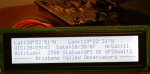
	LCDData(LOWER, "------ Brisbane Valley Observatory -----");

	flag = 0;
	while (1)
	{
		GetGPS(gpsbuf, '$', '*', sizeof(gpsbuf));	// get a sentence from GPS ($ thru *, ignore parity and CRLF)
		
		if (! strncmp(gpsbuf, "$GPRMC", 6))			// sentence starts with $GPRMC
		{
			ptr = GetField(gpsbuf + 7, NULL, 0);	// get next field but ignore data (skip time field)
			ptr = GetField(ptr, stat, sizeof(stat));	// get the stat field
			for (temp = 0; temp < 6; temp++)
			{
				ptr = GetField(ptr, NULL, 0);		// skip the next 6 fields
			}
			GetField(ptr, date, sizeof(date));		// get the date field
			flag += RMC;							// remember that RMC data has been processed
		}

		if (! strncmp(gpsbuf, "$GPGGA", 6))			// sentence starts with $GPGGA
		{
			ptr = GetField(gpsbuf + 7, utc, sizeof(utc));		// get the UTC field
			ptr = GetField(ptr, latitude, sizeof(latitude));	// get the latitude field
			ptr = GetField(ptr, lathem, sizeof(lathem));		// get the lat hem field
			ptr = GetField(ptr, longitude, sizeof(longitude));	// get the longitude field
			ptr = GetField(ptr, lonhem, sizeof(lonhem));		// get the lon hem field
			ptr = GetField(ptr, quality, sizeof(quality));		// get the quality field
			ptr = GetField(ptr, nrsat, sizeof(nrsat));			// get the nbr sat field
			ptr = GetField(ptr, NULL, 0);						// skip the dilution field
			GetField(ptr, hgt, sizeof(hgt));					// get the altitude field
			flag += GGA;										// remember that GGA data has been processed
		}

		if (flag == RMC + GGA)		  // both sentences recieved
		{
			latsec = (UINT)(atoi(latitude + 5)) * MINTOSEC;		// convert ascii latitude minutes to decimal seconds
			sprintf(string, "Lat:%.2s\xDF%.2s\x7%2.2u\"%s",		// dd°mm'ss"h
								latitude,			// degrees	(0 to 90 degrees)
								latitude + 2,		// minutes	(0 to 60 minutes)
								latsec,				// seconds	(0 to 60 seconds)
								lathem);			// hemisphere	(N or S)
													  
			LCDCmd(UPPER, LATPOSN);			// set display cursor to posn
			LCDData(UPPER, string);

			lonsec = (UINT)(atoi(longitude + 6)) * MINTOSEC;	// convert ascii longitude minutes to decimal seconds		 
			sprintf(string, "Lon:%.3s\xDF%.2s\x7%2.2u\"%s",		// ddd°mm'ss"h
								longitude,			// degrees	(0 to 360 degrees)
								longitude + 3,		// minutes	(0 to 60 minutes)
								lonsec,				// seconds	(0 to 60 seconds)
								lonhem);			// hemisphere	(E or W)
			LCDCmd(UPPER, LONPOSN);			// set display cursor to posn
			LCDData(UPPER, string);

			sprintf(string, "UTC:%2.2s:%2.2s:%2.2s", utc,			// hours
													 utc + 2,		// minutes
													 utc + 4);		// seconds
			LCDCmd(UPPER, UTCPOSN);			// set display cursor to posn
			LCDData(UPPER, string);

			sprintf(string, "Date:%2.2s/%2.2s/%2.2s", date + 2,		// month
													  date,			// day
													  date + 4);	// year
			LCDCmd(UPPER, DATEPOSN);		// set display cursor to posn
			LCDData(UPPER, string);

			sprintf(string, "NrSat:%s", nrsat);
			LCDCmd(UPPER, SATPOSN);			// set display cursor to posn
			LCDData(UPPER, string);

			if (*stat == 'A')
			{
				strcpy(status, "GPS OK");
				sprintf(altitude, "%6.0f", atof(hgt) * MTOFT);	// convert meters to feet
			}
			else
			{
				strcpy(status, "GPS NG");
				strcpy(altitude, "------");
			}

			sprintf(string, "Altitude:%s", altitude);
			LCDCmd(LOWER, ALTPOSN);			// set display cursor to posn
			LCDData(LOWER, string);

			sprintf(string, "Status:%s", status);
			LCDCmd(LOWER, STATPOSN);		// set display cursor to posn
			LCDData(LOWER, string);

			sprintf(string, "GPSQual:%s", quality);
			LCDCmd(LOWER, QUALPOSN);		// set display cursor to posn
			LCDData(LOWER, string);

			flag = 0;
		}
	}
}

/***********************************************************
	get data from the serial port, starting when the 'start' character is read,
	copying to the 'dest' buffer, until the 'end' character is read.
***********************************************************/

void GetGPS(char *dest, char start, char end, BYTE len)
{
	BYTE index = 0;
	char rxdata;

	do
	{
		rxdata = GetChar();
	} while (rxdata != start);		// wait for start char

	*(dest + index++) = rxdata;		// store start char

	do
	{
		rxdata = GetChar();
		if (index < (len - 1))		// check for room in buffer
		{
			*(dest + index++) = rxdata;		// store data
		}
	} while (rxdata != end);		// do until end char

	*(dest + index) = 0;			// terminating null
}

/***********************************************************
	get one byte from the serial port (ignore errors)
***********************************************************/

char GetChar(void)
{
	while (! (U0STAT0 & 0x80));		// wait for rx data ready
	return U0RXD;					// fetch the data
}

/***********************************************************
	GetField(src, dest) searches string from 'src' until a comma is found,
	and then returns a pointer to the character after the comma. If 'dest' is
	not NULL, then the characters up to the comma are copied to 'dest' buffer, as well.
***********************************************************/

char *GetField(char *src, char *dest, BYTE len)
{
	BYTE index = 0;

	while (*src != ',')
	{
		if (*src == 0) return src;		// string ends without comma found
		if (dest)			// if valid dest pointer
		{
			if (index < (len - 1))		// check for room in buffer
			{
				*(dest + index++) = *src;	// store data
			}
			*(dest + index) = 0;		// terminating null
		}
		src++;
	}
	return (++src);			// comma found, increment beyond it
}

/***********************************************************
	Write command byte to LCD controller
***********************************************************/

void LCDCmd(BYTE Epin, BYTE arg)
{
	LCDBusy(Epin);			// wait til not busy
	PCOUT = 0;				// select command entry
	PEOUT = arg;			// put byte on the bus
	PCOUT = Epin;			// assert enable
	DELAY;
	PCOUT = 0;				// de-assert enable
}

/***********************************************************
	Write data bytes to LCD controller
***********************************************************/

void LCDData(BYTE Epin, char *arg)
{
	while (*arg)			// data not null
	{
		LCDBusy(Epin);		// wait til not busy
		PCOUT = RS;			// select data entry
		PEOUT = *arg++; 	// put byte on the bus
		PCOUT = Epin + RS;	// assert enable for write
		DELAY;
		PCOUT = RS;			// de-assert enable
	}
}

/***********************************************************
	Check LCD controller busy status.
***********************************************************/

void LCDBusy(BYTE Epin)
{
	PEDD = 0xFF;			// set bus port to inputs
	PCOUT = RW;				// set for status read
	PCOUT = Epin + RW;		// assert enable
	DELAY;

	while (PEIN & 0x80);	// wait for busy bit to go low

	PCOUT = RW;				// de-assert enable
	PCOUT = 0;				// set for write
	PEDD = 0;				// set bus port to outputs
}

/***********************************************************
	Hardware delay using Timer 0
	system clock = 18432000, prescale = 128
	time resolution = 6.9444 uS per count
***********************************************************/

void Delay(UINT dly)
{
	T0H = 0;
	T0L = 1;				// set starting count
	T0RH = (dly & 0xFF00) >> 8;
	T0RL = dly & 0xFF;		// set reload count
	T0CTL = 0xB8;			// enable count, prescale 128, one-shot mode

	while (T0CTL & 0x80);	// wait for timer to disable itself
}
 

Attachments

Last edited:
Top