CFAH4004A-YYH-JP Initialization

glsdean

New member
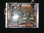
Help! I'm stumped. I'm trying, unsuccessfully, to initialize a CFAH4004A-YYH-JP LCD. So far, all I get is black blocks on rows 1 and 3 indicating, I think, that the LCD is not initialized. I'm interfacing the LCD with a Basic Atom Basic Atom Pro 24 microprocessor using the Basic Atom syntax for LCDINIT and LCDWRITE commands. As shown in the Basic Atom Syntax Manual, the commands are pretty straightforward, and the only modification I've made to my initialization code is to accomodate the two Enable pins for the LCD. I've checked the cabling and output from the microprocessor and have good connections and can cycle all the Enable and Data pins through a high and low sequence. The LCD is being initialized in 4-bit mode, so I've included three LCDINIT commands for each of the HD44780 controllers as showm in the CFAH4004A Manual. I've also tried "strobing" the Enable pins before the LCDINIT commands are invoked. All of this, has not initialized the LCD. Would anyone of this Forum's members tell me what I should try next. A copy of my initialization code is shown below.
Code:
;Display Test - Hello World 2

;PIN CONNECTIONS

;AtomPro-P1 is LCD pin 11 RegSel (R/S)
;AtomPro-P3 is LCD pin 9 Clk1 (E1) 
;AtomPro-P0 is LCD pin 15 Clk2 (E2) 
;AtomPro-P7 is LCD pin 1 Data Line 7
;AtomPro-P6 is LCD pin 2 Data Line 6
;AtomPro-P5 is LCD pin 3 Data Line 5
;AtomPro-P4 is LCD pin 4 Data Line 4
;AtomPro-P2 is LCD pin 10 RdWr


;LCDWRITE MODIFIER CONSTANTS

INITLCD1 CON $133
INITLCD2 CON $132
TWOLINE CON $128
LCDCLEAR CON $101
LCDHOME CON $102
SCR CON $10C

;STROBE LCD ENABLE LINES


HIGH P3				;LCD ROWS 1 & 2, E1
PAUSE 500
LOW P3
PAUSE 500
HIGH P3
PAUSE 500
LOW P3

HIGH P0				;LCD ROWS 3 & 4, E2 
PAUSE 500
LOW P0
PAUSE 500
HIGH P0
PAUSE 500
LOW P0

;LCD INITIALIZATION

pause 500			;PAUSE FOR LCD START	

lcdinit	P1\P3\P7\P6\P5\P4,P2	;INITIALIZE LCD ROWS 1 AND 2

pause 500	

lcdinit	P1\P3\P7\P6\P5\P4,P2

pause 500	

lcdinit	P1\P3\P7\P6\P5\P4,P2


pause 500			;PAUSE FOR LCD START	

lcdinit	P1\P0\P7\P6\P5\P4,P2	;INITIALIZE LCD ROWS 3 AND 4

pause 500

lcdinit	P1\P0\P7\P6\P5\P4,P2

pause 500

lcdinit	P1\P0\P7\P6\P5\P4,P2

pause 500			;PAUSE FOR LCD TO INITIALIZE


lcdwrite P1\P3\P7\P6\P5\P4,P2,[INITLCD1,TWOLINE,LCDCLEAR,LCDHOME,SCR]

lcdwrite P1\P0\P7\P6\P5\P4,P2,[INITLCD2,TWOLINE,LCDCLEAR,LCDHOME,SCR]

Main

lcdwrite P1\P3\P7\P6\P5\P4,P2,[SCRRAM+$00,"-----HELLO WORLD------------------------"]
lcdwrite P1\P3\P7\P6\P5\P4,P2,[SCRRAM+$40,"-----------------HELLO WORLD------------"]
lcdwrite P1\P0\P7\P6\P5\P4,P2,[SCRRAM+$00,"------------HELLO WORLD-----------------"]
lcdwrite P1\P0\P7\P6\P5\P4,P2,[SCRRAM+$40,"-------Brisbane Valley Observatory------"]

goto Main

end
Looking for additional LCD resources? Check out our LCD blog for the latest developments in LCD technology.
 
I'm not really familiar with the Basic Atom language, but according to the user manual the "lcdinit" command does not have a comma in the syntax:

your code: lcdinit P1\P3\P7\P6\P5\P4,P2

manual example: lcdinit P1\P3\P7\P6\P5\P4\P2

I think the strobing of E1 and E2, and the multiple initializations are unnecessary. Try just one instance of the inits.
Code:
lcdinit P1\P3\P7\P6\P5\P4\P2 ;INITIALIZE LCD ROWS 1 AND 2
lcdinit P1\P0\P7\P6\P5\P4\P2 ;INITIALIZE LCD ROWS 3 AND 4

lcdwrite P1\P3\P7\P6\P5\P4,P2,[TWOLINE,LCDCLEAR,LCDHOME,SCR]
lcdwrite P1\P0\P7\P6\P5\P4,P2,[TWOLINE,LCDCLEAR,LCDHOME,SCR]

lcdwrite P1\P3\P7\P6\P5\P4,P2,[SCRRAM+$00,"-----HELLO WORLD------------------------"]
lcdwrite P1\P3\P7\P6\P5\P4,P2,[SCRRAM+$40,"-----------------HELLO WORLD------------"]
lcdwrite P1\P0\P7\P6\P5\P4,P2,[SCRRAM+$00,"------------HELLO WORLD-----------------"]
lcdwrite P1\P0\P7\P6\P5\P4,P2,[SCRRAM+$40,"-------Brisbane Valley Observatory------"]
I wonder if the Atom firmware knows to delay longer after the LCDCLEAR code, as it takes a lot longer to execute in the HD44780 than the others.

I have no idea if this is your problem, just making educated guesses.
 

glsdean

New member
Checked Out the LCDINIT Syntax

Hi Cosmicvoid,
Thanks for your reply. I tried replacing the comma in the LCDINIT syntax with a slash "\" as suggested and recompiled the program. The compiler returned an error indicating that the slash is incorrect. The program compiles without error when the comma is used in the syntax as shown in the Manual. Shown below is a copy of the LCDINIT syntax from the Basic Atom Syntax Manual:

Lcdinit
LCDINIT RegSel\CLK\DB7\DB6\DB5\DB4,RdWrPin

Initilize the LCD display.

RegSel can be a constant or variable specifying the pin for the “R/S” liine of the LCD.

CLK can be a constant or variable specifying the pin for the “E” line of the LCD.

DB7-DB4 can be constants or variables specifying the data lines of the LCD.

RdWrPin can be a constant or variable specifying the pin for the “R/W” line of the LCD.

I have no idea about the delay time associated with the LCDCLEAR modifier for the LCDWRITE command. The Manual does not indicate whether or not there is a delay or its length.

Any other suggestions? Can any other Forum members comment on or offer suggestions for interfacing the Basic Atom microprocessor with the CFAH4004A LCD?
 
Evidently you are looking at the version 7.2 manual for the LCDINIT syntax, and I was looking at the version 8.0 manual. Or maybe you can provide a link to the actual manual you are using. I hate to seem fussy here, but these manuals are pitifully lacking a good explanation of what the LCDINIT operation performs.

According to the data sheet for HD44780 type character LCDs, the init sequence is:

1. Wait 15 mS after Vdd is applied.
2. Write $3x to LCD (only D4~D7 is used).
3. Wait 4.1 mS.
4. Write $3x to LCD (only D4~D7 is used).
5. Wait 100 uS,
6. Write $3x to LCD (only D4~D7 is used).
7. Write $2x to LCD (only D4~D7 is used) to set 4 bit mode.

after that:
Write two nibbles (only D4~D7 is used) for each data/command.

So, regarding the Atom, which of the steps 1~7 is performed by the LCDINIT operation??? All of them?? Only a single 'write $3x'?? Do you have a scope, so that you can see what is happening on the I/O pins in real time?

If I were troubleshooting this project, I'd skip using the LCDINIT operation, and program it using discrete I/O commands, just to see if that works.

low p7, low p6, high p5, high p4, low p0, low p1, low p2, low p3 ;data=$30
pause 15
pulsout p3,10 ;strobe E1
pause 5
pulsout p3,10 ;strobe E1
pauseus 100
pulsout p3,10 ;strobe E1
pauseus 2
low p4 ;data=$20
pulsout p3,10 ;strobe E1
etc, etc.
 
Last edited:

glsdean

New member
Old Manual, Old IDE

Thanks Cosmicvoid for your suggestions. You're correct the Syntax Manual and IDE were ver. 7.2.0.6, which shows a different syntax for the LCDINIT command than does the most recent ver. 8.0.1.0. I'll make the syntax change for the "\" instead of the "," with the new IDE and see if that helps. I have been able to strobe the Enable, Data, R/S and R/W pins using High and Low commands. The strobing indicates that signal is coming across all the pins. I do not know what is happening when the LCDINIT command is invoked, as you have seen that the Manual lacks an explanation and because I do not have an O'scope. Let me get back with you after I reprogram the Basic Atom with the new compiler and see if that makes a difference. Again, thanks for all your suggestions.
 
The more I think about it, the more suspicious I am of the LCDINIT function, and unless I could find out more about what exactly it does, I would not use it, particularly since it didn't work as expected. Just my humble opinion, but I like to be in complete control of my code.

I noticed in the BasicAtom forum, that some people suggested using LCDWRITE function to do the init. That seems inappropriate to me, because the 4 bit interface method requires two consecutive writes (high nibble, low nibble). This is not how the init bytes are supposed to be written (i.e. there are delays required between nibbles). Once the initial nibbles are written, and the mode is set as "4 bit", then LCDWRITE would be appropriate.

But even using LCDWRITE as a multi-command string:
lcdwrite P1\P3\P7\P6\P5\P4,P2,[TWOLINE,LCDCLEAR,LCDHOME,SCR]
is problematic, because unless you know how fast the bytes are written, there could be timing problems. Some commands require 1.5 mS to execute, some need 39 uS, and some need 43 uS. Now, if the LCDWRITE firmware actually did a status read from the LCD before writing, to see it the busy flag is clear, then all would be well. But there is no way to tell if that is happening, without a scope. So you would have to do your own LCDREAD to test the busy status, or else delay to allow for HD44780 execution time.

Too many questions, too few answers. Have you seen any LCD program samples that might shed light on these issues?
 
Last edited:

glsdean

New member
Still Stumped

I've tried using the LCDWRITE command with initlcd (1 or 2) modifiers to no avail. I've also tried pauses from 2000 mS to 5000 mS between the LCDINIT and LCDWRITE commands to give the H44780 controller time to respond, also unsuccessful. The use of the ver. 8.0.1.0 compiler likewise was unsuccessful. Any other suggestions you might have would be appreciated. I've also posted this problem to the Basic Micro Forums, but so far haven't received any response. How could something so simple be such a problem!
 
The manual says, in the LCDWRITE section, that "You must initialize the display with LCDINIT before using this command." That's because if the LCD is not init'd, then obviously subsequent writes will not work; but I also wonder if the firmware keeps a 'record' of the init parameters, else why would the {RdWrPin} parameter be optional for a write operation. How would it do a write without knowing which pin was {RdWrPin}?

The use of LCDWRITE P1\P3\P7\P6\P5\P4,P2,[INITLCD1,INITLCD2] would seem to be the proper sequence of init nibbles (3,3,3,2), but there are no delays in that string, so I wouldn't expect it to work.

But lets just ignore these deep questions for now, and try to get something written to the screen. I am supposing you didn't try my suggested sequence from post #4. So why don't you give that a go, and see what happens. Lets just do 1/2 of the display at first (one controller). Note that there is no LCDINIT command in this code; this is replacing that function. If the firmware requires the LCDINIT command, to store the parameters, then this may cause the LCDWRITEs to fail. You shall see.

Code:
dirl $FF   ;set p0~p7 as outputs
outl $30   ;8 bit i/o: data=$30, control sigs all low
pause 15
pulsout p3,10 ;strobe E1
pause 5
pulsout p3,10 ;strobe E1
pauseus 100
pulsout p3,10 ;strobe E1
pauseus 2
outb $2    ;4 bit i/o: data=$2x: set 4 bit mode
pulsout p3,10 ;strobe E1
pauseus 50   ; 50 uS delay
lcdwrite P1\P3\P7\P6\P5\P4,P2,[Twoline]
pauseus 50   ; 50 uS delay
lcdwrite P1\P3\P7\P6\P5\P4,P2,[Home]
pause 2    ; two mS delay for homing
lcdwrite P1\P3\P7\P6\P5\P4,P2,[Scr]
pauseus 50   ; 50 uS delay
lcdwrite P1\P3\P7\P6\P5\P4,P2,[$41,$42,$43]   ;"ABC"
That should get rid of the dark cells in the top row of the screen, if the init was successful, and print "ABC" if the LCDWRITEs are working. If the writes are not working, then we'll need to make a subroutine that can replace the LCDWRITE function. I'll wait for your result before suggesting any more code.

Edit: Oh, one afterthought... what are you doing with D0~D3 on the LCD?? These unused pins should be tied low. Also, I wonder if your original attempts failed because you don't have any command to set your port pins as outputs. Maybe thats why your voltage readings were so squirrelly.
 
Last edited:

glsdean

New member
I'll Give It a Try & Code That Works (Supposedly)

Hi Cosmicvoid!
Thanks for all your help and suggestions! I have tried pulsing the outputs, as you sugessted previously, and that was successful. When toggled High the Enable, Data, R/S and R/W pins go to 4.9 VDC for the pulse length, as measured by DMM. I've also tried initializing just the upper half of the display using LCDINIT without success. I'll give the suggestions in your most recent reply a try and see what happens. In the meantime, I'm attaching a Doc file that includes code the supposedly works using the Basic Micro syntax. Note that I am using an identical/similar pin configuration for my LCDINIT and LCDWRITE commands. My final application and code, after the initialization problem is solved, is similar to the application described in the Doc to decode and display NMEA sentances from a GPS device.
 

Attachments

glsdean

New member
Tried it - No Success

Hi Cosmic!
I tried your code suggestion and unfortunately it didn't work. Still only got black boxes across rows 1 and 3. I think I understand what the code was attempting to do by setting the ports/pins (input/output) direction and state (high/low). That this, in conjunction, with the PULSEOUT command would initialize the LCD while bypassing the LCDINIT command. Truly saddened that it wasn't successful. Anything else code-wise you can think of that I could/should try?

At this point, I'm thinking that the Basic Atom microcontroller/CFAH4004A is not a good combo, and that I should replace the Basic Atom with a different microcontroller. Can you recommend a microcontroller that you know has a successful record for working "seamlessly" with the CFAH4004A and that is programmable in a basic-type syntax like the Basic Mico microcontrollers.

Sincerely, thanks for your help.
 
I'm sorry that my code fragment was not successful. There are only two things that I can think of at this point (other than double checking that your wiring to the LCD is correct).

1. Borrow an oscilloscope, so that you can see whether the signal states and timing is what is expected. There isn't any other way to tell what your signals are doing dynamically.

2. Change my code fragment to replace the LCDWRITE statements with discrete code, so that you have explicit control over what is happening to the LCD. I know that is much messier than using the cute built-in functions, but it may be a way to salvage the project with this cpu. Let me know if you want to go that route.

I cannot recommend a different microcontroller of that sort, as I don't ever use them myself, and have no experience with them. I typically do embedded projects, or use microcontroller development boards (like Zilog Z8 or Moto HCS12), and then do the programming in assembler or C, and burn the compiled code into the cpu. These development board projects allow the use of a debugging pod, so that the code can be single stepped, line by line. I dont know whether the Basic Atom, or the Basic Stamp, or whatever others, allow that kind of debugging.

One thing I've learned is you need to have the tools to troubleshoot with, because even the simple projects seem to always have stupid bugs in them.

Afterthought: Just to educate myself a little (after having seen the pitiful documentation for the Basic Atom), I looked at the documentation for the Parallax Basic Stamp 2 ( http://www.parallax.com/dl/docs/prod/stamps/web-BSM-v2.2.pdf ) and was actually pretty impressed with their explanation, diagrams, and sample code for their LCDCMD, LCDIN, and LCDOUT functions. Plus, it has capability for two different E strobes. The features of the BS2 seem very similar to the Basic Atom, but the documentation is clearly superior. You might consider it if you decide to switch to a different controller.
 
Last edited:

glsdean

New member
Let's Try Discrete Code

Hi Cosmicvoid!
I'm ready to try just about anything code-wise to salvage this project. If that means using discrete instructions to initialize the beast , then I'm ready. If I understand correctly, discrete coding of the initialization would use the OUT comands to send the binary sequence for initialization, as shown in the CFAH4004A Manual, from the microcontroller to the LCD. Is that right? Let me know how to attempt this, and I'll give it a try. The alternative is scarping this controller and switching to a Basic Stamp. Thanks for you help and staying with me during this problem.
 
As I was looking at the Basic Atom manual, I notice that I made a few mistakes on my earlier code (like "outl $30" instead of "outl = $30"), so I can see why it might not work, although I suppose it should have generated a compiler error. Anyway, here is my latest attempt. One thing about the built-in LCDWRITE function is that it handles a list of variable types, which is beyond the capability for simple discrete code. But I did make a subroutine for handling text string output. It doesn't seem that Atom Basic has pointers, so I used a global variable. It reminds me of why I hate BASIC.
Code:
string var byte(50)

main
	dirl = $FF	;set p0~p7 as outputs
	outl = $30	;8 bit i/o: data=$30, control sigs all low
	pause 15
	pulsout p0,10	;strobe E
	pause 5
	pulsout p0,10	;strobe E
	pauseus 100
	pulsout p0,10	;strobe E
	pauseus 2
	outb = $2	;4 bit i/o: data=$2x: set 4 bit mode
	pulsout p0,10	;strobe E
	pauseus 50	; 50 uS delay
	gosub lcdout [0,P0,$28]	;set 4 bit 2 line mode
	pauseus 50	; 50 uS delay
	gosub lcdout [0,P0,2]	; home
	pause 2		; two mS delay for homing
	gosub lcdout [0,P0,1]	;clear
	pause 2		; two mS delay for clear
	gosub lcdout [0,P0,12]	; display on
	pauseus 50   ; 50 uS delay
	string = "-----HELLO WORLD-----",0
	gosub lcdstring(P0)
	gosub lcdout [0,P0,$C0]	; set cursor to 2nd line
	string = "--Brisbane Valley Observatory--",0
	gosub lcdstring(P0)
wtloop
	goto wtloop

; lcdout subroutine assumes port pins P7~P4 are data
; P1 is RS, P2 is WR, P0 or P3 is E
; does two writes: high nibble/low nibble
type var byte	;cmd=0 or data=2 (value of P1)
epin var byte	;pin for E strobe
data var byte	;data to port
temp var byte

lcdout [type, epin, data]
	temp = (data&$F0)+type	;high nibble + RS
	outl = temp		;out to port, WR and E are low
	pulsout epin,10		;strobe E
	pauseus 5
	temp = ((data<<4)&$F0)+type	;low nibble + RS
	outl = temp		;out to port, WR and E are low
	pulsout epin,10		;strobe E
	pauseus 5
return

; lcdstring subroutine for sending text to lcd
; assumes string in var "string" which must have a null as last byte
index var byte

lcdstring [epin]
	index = 0
	while string(index) > 0
		gosub lcdout [2,epin,string(index)]	;send data byte
		index = index + 1
	wend
return
I hope you have better luck with this. If it works, then we might could get fancier and do testing of the busy flag instead of using delays. It's a shame that I'm writing this 'blind', with no way of testing anything.
 
Last edited:

glsdean

New member
I'l try it!

Thanks Cosmicvoid! I'm away from home this week, on assignment, but will be able to try the code this weekend. The compiler did give errors with the "outl $30" and similar lines, but I corrected them by adding the "=" sign. This eliminated the compiler errors, but still didn't initialize the display. Concerning programming languages, I'd use one of the "C" languages if I could understand it, that's why I'm trying to stay with BASIC. Thanks again, can't wait to try this when I return home.
 
As I take another look at that code, I see that I'm a bit inconsistant with the delays. Most of the write actions take 39 or 43 uS to execute in the HD44780, so the last delay in 'lcdout []' function should be 50 uS instead of 5 uS. That could make the difference as to whether it works or not. Hopefully, we can get rid of the delays in the next iteration.

If you anticipate doing projects any more complicated than this one, you should consider learning a better language, like C. It is so much more versatile.

So, you have to wait til the weekend, eh? You mean you didn't pack up your project and take it with you :rolleyes: ?
 

glsdean

New member
Didn't bring it with me

Hi Cosmic,
Yep, I left the project at home. Didn't want to have a hassle with TSA at the airport - I can imagine how it looks going through the x-ray machine. I'll be sure to make the change for the delay from 5uS to 50 uS. Will let you know what happens. Thanks again.
 

glsdean

New member
Just a question....

Hi Cosmicvoid!
I've been doing a bit more research and am wondering if you think what I'm attempting to do would be easier using a single board computer instead of the Basic Atom microcontroller. Looking through the net, I've found examples of using a SBC and QBASIC to initialize and write to an LCD with only a few simple command lines. In case I didn't state it before, my goal with the CFAH4004A and SBC or microcontroller is to receive NMEA sentences from a GPS device and parse the sentences to display date, time, and position data on the LCD. Let know your thoughts on switching to an SBC for this task.
Best Regards
 
... initialize and write to an LCD with only a few simple command lines.
Ho ho ho, that's what the Atom was supposed to do, eh?

The Atom and the Stamp are both SBCs, although optimized for minimum real estate. I'm not sure which models you're considering, and what their size is, and what is the desired size for your whole project. Handheld, battery operated? Size of Mac mini? What advantage would a larger SBC bring to the table? They usually have more peripheral functions, which you wouldn't need. You just need a serial port and 16 bits of parallel I/O, right?

The main issue seems to be programming, i.e. finding one who's LCD functions do what is expected. I'd be inclined to try the Stamp before moving on to something larger. But that's your call. Can you post links to other SBCs that appeal to you?

I keep wondering to myself just what the LCD functions do, in detail. I surmise the the init function doesn't write anything to the LCD, it just sets internal parameters in the SBC. The read and write functions do the actual I/O. But I wonder if they're sophisticated enough to do the busy flag check before doing a write. The only way to tell would be to use a scope. I also wonder if the documentation doesn't divulge the timing details of the LCD functions because they would be beyond the ken of typical users. I always want to know exactly what the hardware is doing; that's why I write my own functions.
 

glsdean

New member
Tried It - No Success

Hi Cosmicvoid,
My apologies for taking so long to get back to you. I finally had a chance to try the latest code segement you sent, unfortunately it did not initialize the CFAH4004A or print inany text to disply. The Basic Atom compiler balked at Lines 25 and 28 "gosub lcdstring(p0)", but Iwas able to correct the error by changing the syntax to "gosub lcdstring[p0]". Even so, after the correction the display failed to initialize and only showed black boxes across Rows 1 and 3.

I know you've invested quite a bit of time trying to help with this problem, and it is very much appreciated. However, I wonder if there is much more we can do with getting the Basic Atom Pro to talk to the LCD. I've racked my brain trying to think if there is some simple physical thing I've missed that may be preventing the microcontroller from talking to the LCD. At this point I think I've checked everything and I think all the connections are good. I'm getting signals (voltages) from the Basic Atom to the LCD and there are no shorts in any headers or connections. Is there something else physical I should check?

I'm also considering scrapping the Basic Atom Pro for a less problematic microcontroller. I've heard through the Basic Atom Forums that the Pro microcontroller is quirky and that the plain Basic Atom is easier to work with. That's one option, other options I could use your advice on are switching to a Basic Stamp/PIC microcontroller or a full-fledged single board computer (SBC) such as the Rabbit BL2500 Coyote or the Flashlite 386 Ex from JK Mirco. Both SBCs are programmed via C/C++. If you want to take a look at the Flashlite 386 Ex from JK Micro the link is http://www.jkmicro.com/products/flashlite.html. While at the JK Micro site also take a look at the their LCD software, its link is www.jkmicro.com/downloads/downloads.html. The LCD file is LCD EX.ZIP.

In you previous reply you asked about my application for the LCD/microcontroller (or SBC) and it physical requirements. The application is for the microcontroller is to decode, parse, and format NMEA 0183 strings from a GPS receiver to display UTC date, time, position, altitude, etc on an LCD; independent of the GPS signal being decoded by telescope control software. Physically the microcontroller/LCD is a table top box drawing house current to DC power supplies to power the unit. Mobility and power consumption are not issues for the unit. I'm attaching a Pic of unit for you to see its present configuration.

Again your help is much appreciated. I'm looking forward to your advice on what the next course of action should be.

Best Regards,
glsdean
 

Attachments

I'm sorry that nothing seems to be working. My #1 suspicion is that something is wrong with the wiring between the Atom and the LCD. But without good troubleshooting tools (e.g. oscilloscope or logic analyzer), there is no way to know exactly what is happening.

You could try more basic troubleshooting, like setting up a test program to toggle just one signal (at a time), and use a meter or LED to verify that the correct pin at the LCD is changing. I have the feeling you don't want to invest any more time in the Atom Pro, and I can understand that.

I looked at the Flashlite 386 Ex, and my impressions are: overkill in hardware, and waay too expensive. I never did like Borland C :p , but I'd be glad to see you have an excuse to learn C. I've got lots of LCD code already written in C. About 18 months ago, I bought a Zilog Z8 development board, to help someone program a school project. It was only $40, and comes with a C compiler/IDE/debugging pod. You can get it from Digikey http://www.digikey.com/scripts/DkSearch/dksus.dll?Detail?name=269-4540-ND and the user manual is here http://www.zilog.com/docs/z8encore/devtools/um0151.pdf .

You have described your GPS application several times, and since you're not going 'mobile' with the box, a larger (than a Atom/Stamp) SBC is not a size problem. But I have to wonder, if its AC powered (tied to a wall socket) you won't get to see the readings change much :rolleyes: .

So, pick whichever SBC you wish, and we can proceed. Or if you want to continue troubleshooting the Atom, I can suggest some test routines.

What part of the world are you located in? Maybe we should take this offline (email) so the thread isn't full of 'tried this', 'tried that', 'doesn't work' posts.
 
Top