CFAH2004D-TMI-ET question

mythosmc

New member
Hi, I purchased a CFAH2004D-TMI-ET and while reading the data sheet I got confused on a couple things.

On page 20, section

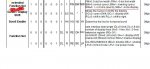
15. Backlight Information

It says that the Supply current ILED should be 32-60mA max test condition 3.5V

Does this mean when I hook up a current meter in series with the anode (pin 15) it should read around 40mA?
Because I adjusted my variable resistor to that current level, and the back light seems pretty dim.

Am I missing something here?

thanks!
Looking for additional LCD resources? Check out our LCD blog for the latest developments in LCD technology.
 
When you say the backlight seems pretty dim, are you judging by the brightness of the characters? Since this is a negative display, the background should always be a dark blue, and the characters will be white. The brightness of the white is really dependant on the setting of the contrast (the setting of the pot that feeds Vo - pin 3). So if your contrast setting is not optimal, the characters may look dim. Is this what you mean?

I assume you have initialized and sent characters to the display, because the contrast of an uninitialized display will not be the same.
 

mythosmc

New member
Ah, I didn't know the brightness was different once it was initialized

The way I hooked it up, when I first started the micro-controller up it shows 2 Lines that are filled in with 16 Boxes, (lines 1, and 3.) However, lines 2 and 4 are blank...

I also noticed that it says Supply Current Idd should be 1.0-1.5mA, I have a 10K Variable resistor hooked up on Pins 1-3 (Vss, Vdd, Vo) As shown in the data sheet, but when I hook up a current meter to it its showing 0.100A 100mA. I tried to adjust it so that I could get it lower, but it stops at 85mA, I guess the variable resistor is not enough.

But when I lower it that low, the contrast is so low that I no longer see those boxes on lines 1, and 3..

Is this normal? (is 100mA too much current going into pin3 Vo?)
 
... when I first started the micro-controller up it shows 2 Lines that are filled in with 16 Boxes, (lines 1, and 3.) However, lines 2 and 4 are blank...
That's normal.
... Is this normal? (is 100mA too much current going into pin3 Vo?)
I would say that is abnormal. But I have never measured the currents in an uninitialized display. My measurements of Io (current from pin 3 to ground) are on the order of 1 mA for an initialized display.

You should init the display and see what the current is.
 

mythosmc

New member
Ok, I was finally able to get it to initialize and display a message, I also realized I was measuring current to pin2 instead of pin3, which doesn't have a resistor as its hooked up straight to +5v. However, I am seeing about 0.020A now (when the text is visible.) I tried to lower it to around 0.001mA but the text just fades out.

Is 0.020A still too high?

Also, how are you reading (current from pin 3 to ground) ? I thought to read current it has to be in series with the circuit?

thanks for helping by the way. :)
 

mythosmc

New member
<edit> was able to get all 4 lines it to work, but still not sure about the current :)
 
Last edited:
... I am seeing about 0.020A now (when the text is visible.) I tried to lower it to around 0.001mA but the text just fades out. Is 0.020A still too high?
Twenty mils seems a bit high. Is that 20 mA to Vdd? I can't think of why it would be so high, unless perhaps there are some floating input pins. I don't know if they have internal pullups or not. I can't imagine pulling 20 mA from the Vo pin.
Also, how are you reading (current from pin 3 to ground) ? I thought to read current it has to be in series with the circuit?
Yup, thats how I do it, put a meter in series to pin 3.

I don't have that display, so I can't do any measurements. But I do have a 40 * 2, do you want me to measure that?

BTW, the Vo circuit is actually just looking for a path to ground. It behaves like it has an internal current source from Vdd, and the external resistance allows the current to flow to ground. It can be a single resistor to ground, a pot is not strictly necessary.
 

mythosmc

New member
Ah, sure. I guess there's a pretty good possibility that my meter is bad too, its a crappy old radio-shack multimeter that never really worked very well :)

The LCD doesn't seem to be heating up or anything, so I assume its running pretty safely right now. Ill try to re-measure the current when I am at school in one of the labs where I have better equipment. ;)

thanks for all your help


One last question though, how come in the data sheet of the LCD CFAH2004D-TMI-ET, the extended instruction set is missing for enabling 4line mode and pixel width etc.. I had to go in a data-sheet from a different company's 4x20 lcd to find the data. Is there some other data-sheet on the crystalfontz website that i missed?

Thanks!
 
Last edited:
the extended instruction set is missing for enabling 4line mode and pixel width etc.. I had to go in a data-sheet from a different company's 4x20 lcd to find the data.
I don't know what you are referring to.

The 4 line displays have two controllers, one for lines 1 & 3 (addr 0x00-0x27), another for lines 2 & 4 (addr 0x40-0x67). These controllers can be set for one line (each) or two lines (each) with the function set command (typically 0x38).

Pixel width? Never heard of that. Maybe you mean font height (5 x 11 vs 5 x 8), but this isn't really a choice as the LCD panel is made with a 5 x 8 cell, so you must select that.

This info is in the CFA data sheet, but is not explained. Am I misunderstanding what you ask? What info did you find in the other sheet that helped you?
 

mythosmc

New member
well I was using this code to address each line

Code:
        if( 4 == line)
		instruction = 0xd4; // write (4nd) line
        if( 3 == line)
		instruction = 0x94; // write (3nd) line	
	if( 2 == line)
		instruction = 0xc0; // write (2nd) line
	if( 1 == line)
		instruction = 0x80; // write top (1st) line
And it would not work, it was overwriting the 1st and 2nd lines of the lcd with data from 3, and 4.

I found another pdf (different companies 20x4) that had in their initialization section an 'extended functions' line (image attached)

Added that to my initialization, and then my code worked...
maybe it was a fluke. I don't know for sure but when I added 0x09 (4bit mode) to my init it all came to life :)
 

Attachments

Last edited:
Top