
Hello!
I am unable to post in the Technical Support forum, so I post here. Moderators can move the thread at will.
I am developing a product with the CFAG320240CX-TFH-T-TS display, and an AT91SAM7S256 as the system processor. They are connected through a Fairchild 74LVXC3245 level shifter like this:
AT91SAM7S256(3.3V) ==> 74LVXC3245 ==> CFAG320240CX-TFH-T-TS(5V)
I have added resistors (82 ohms) on the outputs of the level shifter to reduce the ringing on the LCD signal lines. Helped a bit, but did not eliminate the problem.
Initialization, text and bitmaps are working like a charm.
Configuration:
6800 mode, as shipped. R/W is hardwired low, DISPOFF is hardwired high. JF1 and JF2 are mounted, grounding the bezel and mounting holes. I am using Screen Block 1 for text, starting at address 0x0000 and Screen Block 2 for graphics, starting at address 0x04B0. I have mounted decoupling capacitors on the LCD module, 0.1µF ceramic and 330µF tantal polymer electrolytic.
Touch panel: all 4 wires grounded. Tried leaving them floating, no change.
Graphics test:
Write 0xFF ==> wait 50ms ==> write 0x00 ==> wait 50ms
repeated in an infinite loop. This results in an all-black/all-white screen alternating at 10Hz.
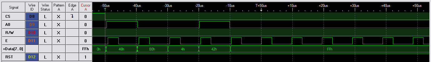
Attached is an image from my logic analyzer showing the first few transitions of the test.
Text test:
Write 'A' ==> wait 50ms ==> write 'B' ==> wait 50ms
repeated in an infinite loop.This results in an all-A/all-B screen alternating at 10Hz.
The problem:
The graphics test will fail after a seemingly random delay of 1-10 seconds, rendering the display with a single black horizontal line with some 'bleeding' outside the display active area. Looks like DC on the panel, not good.
If I increase the write interval, it takes longer before the display crashes.
The strange thing:
Text test does not fail.
That leads me to believe my hardware is OK.
The question:
Has anyone successfully updated graphics on this display, at any rate, over any amount of time?
I am beginning to doubt this is possible, but I would be very happy to be proven wrong.
Any suggestions or ideas are most welcome.
Regards,
Thomas Strand
I am unable to post in the Technical Support forum, so I post here. Moderators can move the thread at will.
I am developing a product with the CFAG320240CX-TFH-T-TS display, and an AT91SAM7S256 as the system processor. They are connected through a Fairchild 74LVXC3245 level shifter like this:
AT91SAM7S256(3.3V) ==> 74LVXC3245 ==> CFAG320240CX-TFH-T-TS(5V)
I have added resistors (82 ohms) on the outputs of the level shifter to reduce the ringing on the LCD signal lines. Helped a bit, but did not eliminate the problem.
Initialization, text and bitmaps are working like a charm.
Configuration:
6800 mode, as shipped. R/W is hardwired low, DISPOFF is hardwired high. JF1 and JF2 are mounted, grounding the bezel and mounting holes. I am using Screen Block 1 for text, starting at address 0x0000 and Screen Block 2 for graphics, starting at address 0x04B0. I have mounted decoupling capacitors on the LCD module, 0.1µF ceramic and 330µF tantal polymer electrolytic.
Touch panel: all 4 wires grounded. Tried leaving them floating, no change.
Graphics test:
Write 0xFF ==> wait 50ms ==> write 0x00 ==> wait 50ms
repeated in an infinite loop. This results in an all-black/all-white screen alternating at 10Hz.
Attached is an image from my logic analyzer showing the first few transitions of the test.
Text test:
Write 'A' ==> wait 50ms ==> write 'B' ==> wait 50ms
repeated in an infinite loop.This results in an all-A/all-B screen alternating at 10Hz.
The problem:
The graphics test will fail after a seemingly random delay of 1-10 seconds, rendering the display with a single black horizontal line with some 'bleeding' outside the display active area. Looks like DC on the panel, not good.
If I increase the write interval, it takes longer before the display crashes.
The strange thing:
Text test does not fail.
That leads me to believe my hardware is OK.
The question:
Has anyone successfully updated graphics on this display, at any rate, over any amount of time?
I am beginning to doubt this is possible, but I would be very happy to be proven wrong.
Any suggestions or ideas are most welcome.
Regards,
Thomas Strand
Looking for additional LCD resources? Check out our LCD blog for the latest developments in LCD technology.
Attachments
-
 la.png8.1 KB · Views: 1,194
")