We fitted a graphic LCD in a coffee vending machine. I work for the manufacturer as an electronic consultant/designer. A custom pcb was designed for this application. The "brain" inside this machine is a PIC 18F820 CPU (128K prog space) running at 19.6Mhz. I've been working for a year on this project. We assembled nearly 40 units to this date.
The problem i have is that sometimes, on some units, i get randomly dots on the screen that are turning on or off. There is no damage done. When the CPU clears the screen and fills it with new data everything is fine.
During prototyping, I would have this problem often. This appened when the flat cable between the pcb and LCD module was too long. 20 Inches was the maximum lenght. This is the lenght we are using right now on our units.
Do you think it still too long ? What do you recommend ?
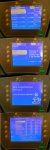
On the picture attached, you can see the CFL driving PCB far from the LCD module. The problem appears more often when the high voltage white cable are near the LCD unit. During assembly we make sure the high voltage cable are "taped" away.
The LCD is held by 4 nylon screw and nuts. The front panel is ABS plastic. The other flat cable comming from under the LCD is the membrane keyboard. Low frequency/voltage signals are used to scan the keys.
I saw coffee machines worked perfecly in our factory and then got this dot on/off problem once the coffee machine was instaled in another environment. It's like if the LCD module is picking up electrical noise from other equipement near. Should i put some sort of sheilding behind the pcb of the LCD ?
I can supply you with the details of the electrical connection between the control pcb and LCD if needed.
I attached a picture to show you the way we hook the LCD. I would like to show you more of the project but can't find a way to attach more than one file to this post.
Thank you for any inputs to help me get rid of this annoying bug.
Yves Belzile
The problem i have is that sometimes, on some units, i get randomly dots on the screen that are turning on or off. There is no damage done. When the CPU clears the screen and fills it with new data everything is fine.
During prototyping, I would have this problem often. This appened when the flat cable between the pcb and LCD module was too long. 20 Inches was the maximum lenght. This is the lenght we are using right now on our units.
Do you think it still too long ? What do you recommend ?
On the picture attached, you can see the CFL driving PCB far from the LCD module. The problem appears more often when the high voltage white cable are near the LCD unit. During assembly we make sure the high voltage cable are "taped" away.
The LCD is held by 4 nylon screw and nuts. The front panel is ABS plastic. The other flat cable comming from under the LCD is the membrane keyboard. Low frequency/voltage signals are used to scan the keys.
I saw coffee machines worked perfecly in our factory and then got this dot on/off problem once the coffee machine was instaled in another environment. It's like if the LCD module is picking up electrical noise from other equipement near. Should i put some sort of sheilding behind the pcb of the LCD ?
I can supply you with the details of the electrical connection between the control pcb and LCD if needed.
I attached a picture to show you the way we hook the LCD. I would like to show you more of the project but can't find a way to attach more than one file to this post.
Thank you for any inputs to help me get rid of this annoying bug.
Yves Belzile
Looking for additional LCD resources? Check out our LCD blog for the latest developments in LCD technology.
Attachments
-
 frontandback.jpg162.2 KB · Views: 697
")