I'm seeing an intermittent problem writing to a CFAG320240 display.
I'm writing to it with an 18F458 PIC Microcontroller and it's easiest to explain the problem with a screen shot or two.
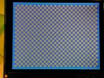
I've included a photo of the checkerboard test pattern, as it should look. (Alternates white/dark squares every 500 ms.)
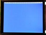
Intermittently, the display locks up and the area outside the legal writing area displays a pattern. Sometimes the diagonal lines shown in the attached photo, and sometimes solid white.
I'm can't immediately see how to attach two photos, so if it does not show up in this one, I'll put the bad image photo in a second message.
The PIC continues to send data to the display, but commands appear not to be executed. All the evidence available to me (looking at data flows with the oscilloscope) indicates that the problem is not with the software logic in my program.
Sometimes, the test pattern will be written to the display, but shifted.
I am intentionally not limiting writes to the retrace interval, as the real application is already slower than I would like. I can live with flicker in exchange for faster data transfer.
I'm running in 6800 mode.
Here's what I've tried, but without success:
1. Verified that all timing intervals are within the limits. Intentionally lengthened the into/out E interval to be 1.6us LOW, followed by 1.6us HIGH. All data is stable before the 1.6US low period.
2. To double check timing issues, the program is now running with the PIC clock at 10 MHz (real program is at 40 MHz) so that all bus writes are nice and slow.
3. I thought the problem might be the cursor not being correctly updated and hence the image data was not being written to a memory address within the display window. I revised the write routine to read back the cursor address and repeat setting the cursor address until it reads the same as the target address. This has not changed the problem.
4. This has some elements of a hardware problem, such as power glitch, so I've tried a couple different ways of powering the display, without any change in behavior.
The period of good operation is variable, and has run between 5 minutes and 1.5 hours.
The code that generates the checkerboard pattern also does a memory clear before writing each checkerboard so if the cursor address were mangled in one write procedure, it would, I believe, be corrected during one of the successive write procedures. This seems not to be happening, as once the display goes into the bad mode, it stays in that mode, regardless of clear memory writes by the PIC. Hence, I've tentatively concluded, when combined with the cursor-read cross check, that the problem is not with cursor addressing.
Another possibility I'm considering is that somehow the setup registers are getting mangled somehow. Not clear how to verify that, as the setup registers can't be read, near as I can tell from the controller data sheet.
I'm hoping that someone else has experienced this problem, and that perhaps the out-of-bounds lines will help identify my problem.
Jack
I'm writing to it with an 18F458 PIC Microcontroller and it's easiest to explain the problem with a screen shot or two.
I've included a photo of the checkerboard test pattern, as it should look. (Alternates white/dark squares every 500 ms.)
Intermittently, the display locks up and the area outside the legal writing area displays a pattern. Sometimes the diagonal lines shown in the attached photo, and sometimes solid white.
I'm can't immediately see how to attach two photos, so if it does not show up in this one, I'll put the bad image photo in a second message.
The PIC continues to send data to the display, but commands appear not to be executed. All the evidence available to me (looking at data flows with the oscilloscope) indicates that the problem is not with the software logic in my program.
Sometimes, the test pattern will be written to the display, but shifted.
I am intentionally not limiting writes to the retrace interval, as the real application is already slower than I would like. I can live with flicker in exchange for faster data transfer.
I'm running in 6800 mode.
Here's what I've tried, but without success:
1. Verified that all timing intervals are within the limits. Intentionally lengthened the into/out E interval to be 1.6us LOW, followed by 1.6us HIGH. All data is stable before the 1.6US low period.
2. To double check timing issues, the program is now running with the PIC clock at 10 MHz (real program is at 40 MHz) so that all bus writes are nice and slow.
3. I thought the problem might be the cursor not being correctly updated and hence the image data was not being written to a memory address within the display window. I revised the write routine to read back the cursor address and repeat setting the cursor address until it reads the same as the target address. This has not changed the problem.
4. This has some elements of a hardware problem, such as power glitch, so I've tried a couple different ways of powering the display, without any change in behavior.
The period of good operation is variable, and has run between 5 minutes and 1.5 hours.
The code that generates the checkerboard pattern also does a memory clear before writing each checkerboard so if the cursor address were mangled in one write procedure, it would, I believe, be corrected during one of the successive write procedures. This seems not to be happening, as once the display goes into the bad mode, it stays in that mode, regardless of clear memory writes by the PIC. Hence, I've tentatively concluded, when combined with the cursor-read cross check, that the problem is not with cursor addressing.
Another possibility I'm considering is that somehow the setup registers are getting mangled somehow. Not clear how to verify that, as the setup registers can't be read, near as I can tell from the controller data sheet.
I'm hoping that someone else has experienced this problem, and that perhaps the out-of-bounds lines will help identify my problem.
Jack
Looking for additional LCD resources? Check out our LCD blog for the latest developments in LCD technology.