Hi
I have a CFAG19232C-YYH-TT LCD and I have been having some difficulty figuring out how to set up the external pot for contrast adjustment.
From reading the data sheet, I understand that I need a 10K or 20K pot. From looking at the diagram on page 8 of the data sheet (8. Contour Drawing & Block Diagram), it appears that I am supposed to connect the signal "Vo" to the pot sweeper pin, Vss (GND) to one side of the pot, and something called "Vout" to the other pot pin. I am not sure what "Vout" is exactly. It is not listed as one of the 16 LCD module pins. Also, if you follow that diagram exactly, you would connect Vdd to Vss...so I'm assuming that's a blooper. I haven't been brave enough to try that yet =P.
I did try connecting Vdd (+5V) to one side of the pot, VSS to the other, and Vo to the sweeper. In this configuration, adjusting the pot value did not yield any noticeable change. I probed the Vo pin on the LCD module (pin 3) and noticed that the Voltage would vary from ~0V to ~5V as I would vary the pot.
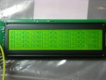
Here is a picture of the display with all pixels (dots) turned on:

and here is a picture when I write 01234567890... to the screen:

As you may or may not be able to see from the pictures, the display sort of fades in and out at certain points - that is, some pixels are darker than others. If you look closely, you can see that the pixels are lighter towards the middle of the screen and darker toward the outsides. I'm assuming that this might be related to contrast settings.
So, in summary, my main questions are these:
1) How do I need to set up the contrast circuitry?
2) What is "Vout" and do I need to do anything with it?
3) Is the display supposed to look like the pictures I attached (faded in some areas) or am I dong something wrong?
Help in this matter is greatly appreciated. Thanks!
- jc123
I have a CFAG19232C-YYH-TT LCD and I have been having some difficulty figuring out how to set up the external pot for contrast adjustment.
From reading the data sheet, I understand that I need a 10K or 20K pot. From looking at the diagram on page 8 of the data sheet (8. Contour Drawing & Block Diagram), it appears that I am supposed to connect the signal "Vo" to the pot sweeper pin, Vss (GND) to one side of the pot, and something called "Vout" to the other pot pin. I am not sure what "Vout" is exactly. It is not listed as one of the 16 LCD module pins. Also, if you follow that diagram exactly, you would connect Vdd to Vss...so I'm assuming that's a blooper. I haven't been brave enough to try that yet =P.
I did try connecting Vdd (+5V) to one side of the pot, VSS to the other, and Vo to the sweeper. In this configuration, adjusting the pot value did not yield any noticeable change. I probed the Vo pin on the LCD module (pin 3) and noticed that the Voltage would vary from ~0V to ~5V as I would vary the pot.
Here is a picture of the display with all pixels (dots) turned on:

and here is a picture when I write 01234567890... to the screen:

As you may or may not be able to see from the pictures, the display sort of fades in and out at certain points - that is, some pixels are darker than others. If you look closely, you can see that the pixels are lighter towards the middle of the screen and darker toward the outsides. I'm assuming that this might be related to contrast settings.
So, in summary, my main questions are these:
1) How do I need to set up the contrast circuitry?
2) What is "Vout" and do I need to do anything with it?
3) Is the display supposed to look like the pictures I attached (faded in some areas) or am I dong something wrong?
Help in this matter is greatly appreciated. Thanks!
- jc123
Looking for additional LCD resources? Check out our LCD blog for the latest developments in LCD technology.
