
Hi,
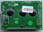
I recently bought the above mentioned display - and realized at home, that it has no generator for the negative voltage, which is necessary to be able see a image on the display as I understand.
So, I have four questions:
1 - is it right, that the neg. voltage is (absolutely) necessary to see the display content?
2 - is the space named U4, C1, C2 left blank for the neg. Voltage generator?
3 - is the Max ICL7660 or compatible, combined with two 10µF caps the right choice? In other words: is there a part list or something available for this display, so I can add the missing parts by myself?
4 - is it possible to use the -12V/5V/GND from the standard ATX power supply of the computer instead?
Thx in advance,
uda.
I apologize for my english, as you may have noticed, I'm no native speaker ;-)
Looking for additional LCD resources? Check out our LCD blog for the latest developments in LCD technology.
")