CFAG12864 with PIC 16F877A

catdsnny

New member
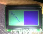
Code below, getting random data and flashing display. any ideas? note that ms_delay is not really a millisecond.
Code:
#include "system.h"

//20mhz 16F877A

//port a is control port
#define CS1 0
#define CS2 1
//#define RESET 2 - connect to RC (10k to +5, .1uf to GND)
//#define RW 3    - connect to GND (write only)
#define RS 4  //called DI on spec sheet
#define E 5

//============================================================
void ms_delay()
  {
  int
    delay;
  for( delay = 0; delay < 500; delay++ )
    nop();
  }
//============================================================
void main()
  {
  //portd is data port
  portd = 0;
  trisd = 0;
  
  adcon1 = 00000110b;   //all A/D lines digital
  
  //porta is control port
  porta = 0;
  trisa = 0;

  set_bit ( porta, E );
  
  //wait for lcd to reset
  
  int
    delay;
  for( delay = 0; delay < 1000; delay++ )
    ms_delay();
    
  clear_bit ( porta, E );
  clear_bit ( porta, RS );
  clear_bit ( porta, CS1 );
  clear_bit ( porta, CS2 );

  //turn display on
  portd = 00111111b;
  ms_delay();
  set_bit ( porta, E );
  ms_delay();
  clear_bit ( porta, E );
  ms_delay();

  //start line 0 (set by reset anyway?)
  portd = 11000000b;
  ms_delay();
  set_bit ( porta, E );
  ms_delay();
  clear_bit ( porta, E );
  ms_delay();

  char
    x;
  char
    y;
  char
    num;
  while(true)
    {
    num = 0;
    for( x = 0; x < 8; x++ )
      for( y = 0; y < 64; y++ )
        {
        //set x page
        portd = (10111000b | x);
        ms_delay();
        set_bit ( porta, E );
        ms_delay();
        clear_bit ( porta, E);
        ms_delay();

        //set y
        portd = (01000000b | y);
        ms_delay();
        set_bit ( porta, E );
        ms_delay();
        clear_bit ( porta, E);
        ms_delay();
        
        //data
        set_bit ( porta, RS );
        ms_delay();
        
        portd = num;
        ms_delay();
        num++;
        
        set_bit ( porta, E );
        ms_delay();
        clear_bit ( porta, E );
        ms_delay();
        
        clear_bit ( porta, RS);
        ms_delay();
        }
    }
  while(true)
    nop();
  }
(Edit by CF Tech: used code tag to fix indentation.)
Looking for additional LCD resources? Check out our LCD blog for the latest developments in LCD technology.
 

CF Support

Administrator
The only issue I see is that you may not be waiting long enough after the screen's initialization before you start writing to the display.

Before your loop to output to the display, try waiting a longer period of time, say 10 milliseconds.
 

CF Tech

Administrator
Here is some AVR code for that controller you could look at as an example:
Code:
//============================================================================
// Crystalfontz S6B0107+S6B0108 Demonstration code
// LOW_LCD.C: Low-level lcd display routines.
// Samsung KS0107+KS0108 (S6B0107+S6B0108) LCD Controller
// Atmel ATMega32 processor @ 16MHz
// WinAVR / AVR GCC + Atmel AVR Studio
// Copyright 2005, Crystalfontz America, Inc. http://www.crystalfontz.com
//============================================================================
#include "avr/io.h"
#include "avr/iom32.h"
#include "string.h"
#include "avr/delay_x.h"
#include "typedefs.h"
#include "utils.h"
#include "low_lcd.h"
//============================================================================
//This is the display memory.
ubyte
  display[8][128];  //1024 bytes
//============================================================================
void write_both_lcd_control_registers(ubyte data)
  {
  //We need to wait until both controller's busy bits are clear.
  //Talk to the status (instruction) register.
  //(Must happen 140nS before the RISING edge of E.)
  PORTC&=~PORTC1_LCD_DI;
  //Tell the LCD we are going to be reading it
  //(Must happen 140nS before the RISING edge of E.)
  PORTC|=PORTC6_LCD_RW;
  //Talk to the left controller only
  //(Must happen 140nS before the RISING edge of E.)
  PORTC&=~PORTC0_LCD_CS1;
  PORTD|=PORTD6_LCD_CS2;
  //Make port A high-impedance
  DDRA=0x00;
  //Enable the selected controller's read data onto the port
  PORTC|=PORTC7_LCD_E;
  //The data is not valid for 320nS
  _delay_cycles(4); //375nS
  //Wait for the busy bit to drop
  while(PINA&0x80);
  //Terminate the read
  PORTC&=~PORTC7_LCD_E;

  //Talk to the right controller only
  PORTC|=PORTC0_LCD_CS1;   //125nS
  PORTD&=~PORTD6_LCD_CS2;  //125nS
  //(Must happen 140nS before the RISING edge of E.)
  //(E LOW pulse must be 450mS min)
  _delay_cycles(2);      //250nS

  //Enable the selected controller's read data onto the port
  PORTC|=PORTC7_LCD_E;
  //The data is not valid for 320nS
  _delay_cycles(4);
  //Wait for the busy bit to drop
  while(PINA&0x80);
  //Terminate the read
  PORTC&=~PORTC7_LCD_E;

  //Tell the LCD that we are writing to it.
  //(Must happen 140nS before the RISING edge of E.)
  PORTC&=~PORTC6_LCD_RW;    //125nS
   //Talk to both controllers
  //(Must happen 140nS before the RISING edge of E.)
  PORTC&=~PORTC0_LCD_CS1;   //125nS
  //stretch LOW E pulse width above the minimum of 450nS
  _delay_cycles(2);        //250nS
  //Strobe the E pin. We are still aimed at the status/instruction register.
  PORTC|=PORTC7_LCD_E;
  //Write the data to the output latches of port A
  //(Must happen 200nS before the FALLING edge of E.)
  PORTA=data;           //62.5nS
  //Go back to port A as an output
  DDRA=0xFF;            //125nS
  //stretch HIGH E pulse width above the minimum of 450nS
  _delay_cycles(3);    //312.5nS
  PORTC&=~PORTC7_LCD_E;
  }
//============================================================================
// PORTC0_LCD_CS1 and PORTD6_LCD_CS2 must be set to select the desired
// controller
//----------------------------------------------------------------------------
void write_lcd_data(ubyte data)
  {
  //We need to wait until the busy bit is clear.
  //Talk to the status (instruction) register.
  //(Must happen 140nS before the RISING edge of E.)
  PORTC&=~PORTC1_LCD_DI;
  //Tell the LCD we are going to be reading it
  //(Must happen 140nS before the RISING edge of E.)
  PORTC|=PORTC6_LCD_RW;
  //Make port A high-impedance
  DDRA=0x00;
  //Enable the selected controller's read data onto the port
  PORTC|=PORTC7_LCD_E;
  //The data from the LCD is not valid for 320nS
  _delay_cycles(4); //375nS
  //Wait for the busy bit to drop
  while(PINA&0x80);
  //Terminate the read
  PORTC&=~PORTC7_LCD_E;
  //Tell the LCD that we are writing to it.
  //(Must happen 140nS before the RISING edge of E.)
  PORTC&=~PORTC6_LCD_RW;   //125nS
  //Aim at the data register.
  //(Must happen 140nS before the RISING edge of E.)
  PORTC|=PORTC1_LCD_DI;   //125nS
  //stretch LOW E pulse width above the minimum of 450nS
  _delay_cycles(2);      //250nS
  //Strobe the E pin.
  PORTC|=PORTC7_LCD_E;
  //Write the data to the output latches of port A
  //(Must happen 200nS before the FALLING edge of E.)
  PORTA=data;            //62.5nS
  //Go back to port A as an output
  DDRA=0xFF;             //125nS
  //stretch HIGH E pulse width above the minimum of 450nS
  _delay_cycles(3);     //312.5nS
  //Terminate the write
  PORTC&=~PORTC7_LCD_E;
  }
//============================================================================
// Takes about 5.08ms (201.7KB/S) reading busy flag
void UpdateLCD(void)
  {
  register ubyte
    *left_data;
  register ubyte
    *right_data;
  register ubyte
    page_address;
  register ubyte
    column_address;

  //Initialize our source data pointers.
  left_data=&display[0][0];
  right_data=&display[0][64];

  //Make sure we are not in a write cycle
  PORTC&=~PORTC7_LCD_E;

  //Make sure the LCD thinks we are writing
  PORTC&=~PORTC6_LCD_RW;

  for(page_address=0;page_address<=7;page_address++)
    {
    //Set Y address (page, or horizontal stripe of 8 pixels) (controller docs call this "X")
    write_both_lcd_control_registers(0xB8|page_address);
    //Set X address 0 (right to left) (controller docs call this "Y")
    write_both_lcd_control_registers(0x40);

    for(column_address=0;column_address<=63;column_address++)
      {
      //Talk to the left controller only
      PORTC&=~PORTC0_LCD_CS1;
      PORTD|=PORTD6_LCD_CS2;
      write_lcd_data(*left_data++);
      //Talk to the right controller only
      PORTC|=PORTC0_LCD_CS1;
      PORTD&=~PORTD6_LCD_CS2;
      write_lcd_data(*right_data++);
      }
    //Skip down to the next line
    left_data+=64;
    right_data+=64;
    }
  }
//============================================================================
void InitializeLCD(void)
  {
  //Display on
  write_both_lcd_control_registers(0x3F);

  //Set Start Line 0
  write_both_lcd_control_registers(0xC0);

  //Clear the display memory
  memset(display,0x00,sizeof(display));

  //Copy the display memory to the physical LCD
  UpdateLCD();
  }
//============================================================================
And here is some sample code from "The Parallel Port" thread: "void CCFAG_WinTestDlg::OnInitialize()" from CFAG_WinTestDlg.cpp in the source CFAG12864B_WinTest.zip.
Code:
void CCFAG_WinTestDlg::OnInitialize() 
  {
  CWaitCursor wait;

  //0 => 0x378, 1 => 0x278. 2 => 0x3BC
  switch(m_address.GetCurSel())
    {
    case 1:
      port_data_address=0x278;
      break;
    case 2:
      port_data_address=0x3BC;
      break;
    default:
      port_data_address=0x378;
      break;
    }
  port_control_address=port_data_address+2;

  ubyte
    i;
  i=0;

  //Reset is an R-C in the hardware.
  //R/W is set permanently low in the hardware (write-only)

  //These things prety much initialize themselves

  //Idle E
  CLR_E;

  //Talk to the control register.
  CLR_RS;

  //Talk to both controllers
  CLR_CS1;
  CLR_CS2;

  //Display on
  DATA(0x3F);
  SET_E;
  CLR_E;
  Sleep(10);

  //Set Start Line 0
  DATA(0xC0);
  SET_E;
  CLR_E;
  Sleep(10);

  int
    row;
  for(row=0;row<=7;row++)
    {
    //Set X address
    DATA(0xB8|row);
    SET_E;
    CLR_E;
    Sleep(1);

    //Set Y address 0
    DATA(0x40);
    SET_E;
    CLR_E;
    Sleep(1);

    //Aim at the data register.
    SET_RS;

    //Talk to controller 1 only
    SET_CS1;

    int
      col;
    for(col=0;col<=63;col++)
      {
      FDATA(cfag12864b[row][col]);
      SET_E;
      Sleep(1);
      CLR_E;
      Sleep(1);
      }

    //Talk to the controller 2
    CLR_CS1;
    SET_CS2;

    for(col=64;col<=127;col++)
      {
      FDATA(cfag12864b[row][col]);
      SET_E;
      Sleep(1);
      CLR_E;
      Sleep(1);
      }
    
    //Talk to both controllers
    CLR_CS1;
    CLR_CS2;

    //Aim back to the control register.
    CLR_RS;
    }
 }
Maybe taking a look at one of those will help.
 

catdsnny

New member
ya- this code was derived from the c++ parallel port code above, plus the spec sheets...the delay at the start is about 5 seconds; i set an LED when is starts and just timed it from the time i applied power...something else is amiss
 

catdsnny

New member
well i have it working...almost...the test pattern displays properly on the right side display, but it jitters on the left side display- i've attached a video of the behaviour. there's also some random dots every now and then...possible explanation: wires too long (about 10" of 22 ga), breadboard capacitance, poor grounding...i dunno- anyone seen anything similar? i slowed it down to about 500ms per operation, and the result was exactly the same, so its not timing. the final code is below for anyone wanting to use it. one hint- dont use RA4 or RA5 - they are open drain and dont drive the LCD- that was my problem before. after moving to RA2 and RA3 everything works like a charm except for this little jitter. any thoughts or past experiences appreciated.
Code:
#include <system.h>

//20mhz 16F877A

//port a is control port
#define CS1 0
#define CS2 1
//#define RESET 2 - connect to RC (10k to +5, .1uf to GND)
//#define RW 3    - connect to GND (write only)
#define RS 2  //called DI on spec sheet
#define E 3

void ms_delay(int Length) {
  int delay;
  for ( delay = 0; delay < Length; delay++ )
    nop();
}


void write ( char data, char rs ) {
  if (rs)
    set_bit ( porta, RS );
  else
    clear_bit ( porta, RS );
    
  portd = data;
  
  clear_bit ( porta, E );
  nop();  nop();  nop();
  
  set_bit ( porta, E );
  nop();  nop();  nop();
  
  clear_bit ( porta, E );
  nop();  nop();  nop();
  
  set_bit ( porta, E );
  nop();  nop();  nop();
    
}

void main() {

  //portd is data port
  portd = 0;
  trisd = 0;
  
  adcon1 = 00000110b;   //all A/D lines digital
  
  //porta is control port
  porta = 0;
  trisa = 0;

  set_bit ( porta, E );
  
  //wait for lcd to reset
  
  int delay;
  for ( delay = 0; delay < 1000; delay++ )
    ms_delay(1000);
    
  
  clear_bit ( porta, CS1 );
  clear_bit ( porta, CS2 );

  write ( 00111111b, 0 ); //display on
  ms_delay(1000);

  write ( 11000000b, 0 );   //start line 0 (set by reset anyway?)
  ms_delay(1000);


  char x;
  char y;
  char num;
  while (true) {
    num = 0;
    for ( x = 0; x < 8; x++ )
      for ( y = 0; y < 64; y++ ) {
        write (10111000b | x, 0);   //set x
        ms_delay(50);
  
        write (01000000b | y, 0);   //set y
        ms_delay(50);
            
        write ( num, 1 );
        ms_delay(50);
        num++;        
      }
  }
}
 

Attachments

CF Tech

Administrator
Probably some noise on the left-side chip select. Try reversing the ship selects and see if the problem moves. If it moves, the problem is outside the display -- check what is different between CS1 and CS2 in your system.

If it stays on the same side of the display, then either the display is damaged, or there is some marginal timing or noise on the controls.

* Try making everything slow in your code, then speed up section by section.

* Try adding a 0.1uF capacitor between power and ground at the pins of the display.

* If you have access to an oscilloscope, look at the E signal for bouncing.

The length is not really that critical, IF E has a clean signal, the power is good, and there is plenty of time for all the signals to settle down before E changes state.
 

catdsnny

New member
swapped the CS1 / CS2 lines, no difference...

I had tried slowing everything down (> 10ms between every operation), exact same result.

.1 across 5v/gnd - no difference

no oscope...need to get one, its an audio app, so i need it anyway

Maybe display fried...all i did was solder the wires to it and plug it to breadboard. Will try another.
 

catdsnny

New member
tried new LCD with exact same results...guess its time to get an oscope...let me know if anyone tries this with success...
 

catdsnny

New member
I have narrowed the problem. The display gives garbage when there are less than three "1"s in the data passed to it. So it appears that the 16F877A cannot sink enough current when passing data like 01000001, etc. It's intermittent on the failures, however, it never fails when there are three or more "1"s in the data. The problem also seems to "accumulate". When I send a string of 00000000 (like to clear the display), the dropped 0s get worse towards the end of each line. But it never fails when I send a string of 11111111. So I can use the display in "inverted" mode so to speak without any trouble at all. More to come once I determine the solution.
 
Top