CFAG12832A-YGH-N and ST7920 4-bits mode

oZIELH

New member
Hi have a CFAG12832A-YGH-N LCD and want to use it in parallel 4-bits mode but unfortunately is not working, I just want to write some simple characters to validate our design because we are sending data thru SPI(MOSI and SCK) to a 8-bits shift register and then to the LCD,

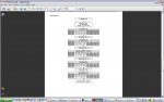
I am following the init steps in the ST7920V40_E.pdf document (see attached image 4-bitsinit.jpg), -by the way your documentation is based on an older version where 4-bits init is not correct-, but i am not able to see what i am trying to write

This is the code I am using to init lcd in 4-bits mode, I am making sure that needed values are in the lcd pins so SPI and shift register is working fine.

An important question is How much time should I wait between the transfer of the higher 4 bits and the lower 4 bits ?

After initialization, what should I do to write a "Hello world" on the LCD, Can you provide a sample code or a pseudocode to do that please (4 bits mode) ??

Code:
LCDWaitLong(300); //wait >40ms
  
 /* write LCD init seq to SPI 0x 20 Function Set*/
  LCD_4bit_Init =0x02;  
  SPIWaitTXDone(); 
  SPISendChar(LCD_4bit_Init);
  LCDWaitTooShort(1); 
  LCDToggleEN();
  LCDWaitShort(1);
                                                                      
  SPIClearRecieveDataReg(&u8TempValue);/* Clear receive data register. */    
  LCD_4bit_Init =0x00;
  SPIWaitTXDone(); 
  SPISendChar(LCD_4bit_Init);
  LCDWaitTooShort(1); 
  LCDToggleEN(); 
  
      /* write LCD init seq to SPI 0x 20 Function Set*/
  LCD_4bit_Init =0x02;  
  SPIWaitTXDone(); 
  SPISendChar(LCD_4bit_Init);
  LCDWaitTooShort(1); 
  LCDToggleEN();
  LCDWaitShort(1);
                                                                      
  SPIClearRecieveDataReg(&u8TempValue);/* Clear receive data register. */    
  LCD_4bit_Init =0x00;
  SPIWaitTXDone(); 
  SPISendChar(LCD_4bit_Init);
  LCDWaitTooShort(1); 
  LCDToggleEN();             
     
  /* write LCD init seq to SPI 0x 20 Function Set*/
  LCD_4bit_Init =0x02; 
  LCDWaitShort(5); //wait 100 us
  SPIWaitTXDone(); 
  SPISendChar(LCD_4bit_Init);
  LCDWaitTooShort(1); 
  LCDToggleEN();
  LCDWaitShort(1);
                                                                      
  SPIClearRecieveDataReg(&u8TempValue);/* Clear receive data register. */    
  LCD_4bit_Init =0x00;
  SPIWaitTXDone(); 
  SPISendChar(LCD_4bit_Init);
  LCDWaitTooShort(1); 
  LCDToggleEN();   
  
  
   /* write LCD init seq to SPI 0x 0F Display On/Off Control*/ 
  LCDWaitShort(5);//wait 100 ms  
  LCD_4bit_Init = 0x00;
  SPIWaitTXDone(); 
  SPISendChar(LCD_4bit_Init);
  LCDWaitTooShort(1); 
  LCDToggleEN();
  LCDWaitShort(1);
                    
  SPIClearRecieveDataReg(&u8TempValue); /* Clear receive data register.*/        
  LCD_4bit_Init =0x0F;
  SPIWaitTXDone(); 
  SPISendChar(LCD_4bit_Init);
  LCDWaitTooShort(1);                               
  LCDToggleEN(); 
  
  
  /* write LCD init seq to SPI 0x 01 Display Clear*/                            
  LCDWaitShort(5);//wait 100 ms 
  LCD_4bit_Init = 0x00;
  SPIWaitTXDone(); 
  SPISendChar(LCD_4bit_Init);
  LCDWaitTooShort(1); 
  LCDToggleEN();
  LCDWaitShort(1);
                               
  SPIClearRecieveDataReg(&u8TempValue); /* Clear receive data register. */      
  LCD_4bit_Init =0x01;
  SPIWaitTXDone(); 
  SPISendChar(LCD_4bit_Init);
  LCDWaitTooShort(1); 
  LCDToggleEN();
  
  
   /* write LCD init seq to SPI 0x 06 Entry Mode Set*/
  LCDWaitLong(60);//wait 10 ms  
  LCD_4bit_Init = 0x00;
  SPIWaitTXDone(); 
  SPISendChar(LCD_4bit_Init);
  LCDWaitTooShort(1);
  LCDToggleEN();
  LCDWaitShort(1);
                                                                  
  SPIClearRecieveDataReg(&u8TempValue);/* Clear receive data register. */
  LCD_4bit_Init =0x06;   // 
  SPIWaitTXDone(); 
  SPISendChar(LCD_4bit_Init);  
  LCDWaitTooShort(1);
  LCDToggleEN();
Looking for additional LCD resources? Check out our LCD blog for the latest developments in LCD technology.
 

Attachments

CF Support

Administrator
The first thing that I noticed is that you're trying to use a 4-bit parallel example while using SPI to communicate with the display.

Please see page 26 of the controller datasheet for information on using the serial interface. The page following has some example code for an 8051 controller.
 
Your hardware hookup description is a little confusing, but the way I interpret it is that in 4 bit mode, you are still using the cpu SPI to send bits to an external shift register, which is connected to the display as 4 bits parallel. Is this correct?

As for timing between the two nibbles of a byte, it looks like you can send them using the minimum E cycle timing - 1200 nS between nibbles. Between bytes, you would have to wait the duration of the instruction execution time, i.e. 72 uS (except for 'clear', 1.6 mS), unless you are testing the busy flag, which your hookup probably does not allow for.

As for writing a string to the screen, you just write the two nibbles with RS set to 1. BTW, in your code snippit, there doesn't seem to be any handling of the RS signal, to differentiate between instruction and character data. Are you controlling RS and RW from your cpu?
 

CF Tech

Administrator
Thank you for your message.

I think you can clock your SPI at up to 1.6MHz.

Each byte written to the ST7920 will take three 8-bit SPI transfers.

Follow the sequence for initializing 8-bit parallel.

Please try to follow this example, I just coded it as an example, but I think it should work:

Code:
#define SET_CS //Do whatever it takes to put CS high
#define CLR_CS //Do whatever it takes to put CS low

void SPI_Write(unsigned char data)
  {
  //Do whatever it takes to clock 8 bits out your
  //SPI port, at up to 1.6MHz clock.
  }


void Write_ST7920_Command(unsigned char command)
  {
  unsigned char
    first_byte;
  unsigned char
    second_byte;
  unsigned char
    third_byte;

  SET_CS;
   
  delay_us(1); //may not be needed

  first_byte=0xF8; // 1111 1000
  SPI_Write(first_byte);

  second_byte=comand&0xF0; // four MSb, for 0 pad
  SPI_Write(second_byte);

  third_byte=(comand<<4)&0xF0; // four MSb, for 0 pad
  SPI_Write(third_byte);

  delay_us(1); //may not be needed

  CLR_CS;
  }

void Write_ST7920_Data(unsigned char data)
  {
  unsigned char
    first_byte;
  unsigned char
    second_byte;
  unsigned char
    third_byte;

  SET_CS;
  
  delay_us(1); //may not be needed

  first_byte=0xFA; // 1111 1010
  SPI_Write(first_byte);

  second_byte=data&0xF0; // four MSb, for 0 pad
  SPI_Write(second_byte);

  third_byte=(data<<4)&0xF0; // four MSb, for 0 pad
  SPI_Write(third_byte);

  delay_us(1); //may not be needed

  CLR_CS;
  }

void main(void)
  {
  //power on
  delay_ms(40);

  Write_ST7920_Command(0x30);
  delay_us(100);

  Write_ST7920_Command(0x30);  
  delay_us(37);

  Write_ST7920_Command(0x0C);  
  delay_us(100);

  Write_ST7920_Command(0x01);  
  delay_ms(10);

  //Set Entry mode
  Write_ST7920_Command(0x06);  
  delay_ms(10); //safe, might be able to reduce


  // Set Extended function set
  Write_ST7920_Command(0x30);  
  delay_ms(10); //safe, might be able to reduce

  Write_ST7920_Command(0x32);  
  delay_ms(10); //safe, might be able to reduce

  Write_ST7920_Command(0x36);  
  delay_ms(10); //safe, might be able to reduce

  for (int x=0;x<32;x++)
    {
    //Set Y address
    Write_ST7920_Command(0x80|x);  
    delay_ms(10); //safe, might be able to reduce

    //Set X address 0
    Write_ST7920_Command(0x80);  
    delay_ms(10); //safe, might be able to reduce

    for(i=0; i<18;i++)
      {
      Write_ST7920_Command(0xAA);
      delay_ms(1); //safe, might be able to reduce
      }
    }
  }
 

oZIELH

New member
st7920

Thanks CosmicVoid for your answer about timing between nibbles,

I have the spi port connected to a 8-bit shift register that is connected to the LCD in 4-bits mode, each spi transfer look like this [x,x,x,RS,d7,d6,d5,d4] and the lcd´s E signal is controlled by another gpio, for now RW is not used and tied to gnd.

CF tech,
The SET_CS putting in high lcd´s E signal ?if so my question is E signal should be high all the time while spi transfers are being performed ??

What´s the purpose of this first spi write in both Write_ST7920_Data and Command?

first_byte=0xF8; // 1111 1000
SPI_Write(first_byte);

Is this code neccesary to write a simple "Hello World" on the lcd ?, Can you explain what those "For" are doing ?

To write a simple character like ´H´ should I send just a byte (char´s ascii value ?)?

Code:
// Set Extended function set
  Write_ST7920_Command(0x30);  
  delay_ms(10); //safe, might be able to reduce

  Write_ST7920_Command(0x32);  
  delay_ms(10); //safe, might be able to reduce

  Write_ST7920_Command(0x36);  
  delay_ms(10); //safe, might be able to reduce

  for (int x=0;x<32;x++)
    {
    //Set Y address
    Write_ST7920_Command(0x80|x);  
    delay_ms(10); //safe, might be able to reduce

    //Set X address 0
    Write_ST7920_Command(0x80);  
    delay_ms(10); //safe, might be able to reduce

    for(i=0; i<18;i++)
      {
      Write_ST7920_Command(0xAA);
      delay_ms(1); //safe, might be able to reduce
      }
    }
  }
 
CF tech,
The SET_CS putting in high lcd´s E signal ?if so my question is E signal should be high all the time while spi transfers are being performed ??
It looks like CF Tech thinks you are using SPI directly to the display, instead of to your external shift register. The E signal is low while you are loading your shift register, then when the SR is loaded, the E is taken high for a minimum of 140 nS, then back low. Do not keep the E signal high all the time, it is a strobe, not an "enable".
What´s the purpose of this first spi write in both Write_ST7920_Data and Command?

first_byte=0xF8; // 1111 1000
SPI_Write(first_byte);
That is the way the direct-to-display SPI is done, with 3 bytes. You are not using this method.
To write a simple character like ´H´ should I send just a byte (char´s ascii value ?)?
Yes, but the RS bit must be high for characters.

Since everything you send in 4 bit mode requires the two nibble writes, you would be better off making a single function to handle both nibbles and both command and character data. Like this:
Code:
void write_7920(BYTE data, BYTE rs_state)
{
  SPISendChar((data >> 4) | rs_state); // rs_state is 0 or 0x10
  SPIWaitTXDone(); 
  LCDToggleEN();
                                                                      
  SPISendChar((data & 0x0F) | rs_state);
  SPIWaitTXDone(); 
  LCDToggleEN(); 
}
 

CF Tech

Administrator
cosmicvoid:

I think there might be come communications problems here (I do not mean electrical!).

I think he must be using SPI mode of the controller.

There would be no reason for using an external shift register.

oZIELH

Please let us know: Do you have a separate component that is a shift register, or are you using the ST7920 SPI mode?
 
cosmicvoid:

I think there might be come communications problems here (I do not mean electrical!).
I think he must be using SPI mode of the controller.
There would be no reason fro using an external shift register.
Yes, you're right, there is no reason to use hardware SR. But I took the OP's explaination at face value:
I have the spi port connected to a 8-bit shift register that is connected to the LCD in 4-bits mode, each spi transfer look like this [x,x,x,RS,d7,d6,d5,d4] and the lcd´s E signal is controlled by another gpio, for now RW is not used and tied to gnd.
Maybe we can convince him to try a direct cpu-to-display via SPI ;).
 

oZIELH

New member
st7920 in SPI mode

All,

Thanks for your answers, The issue was resolved, finally was a Hw issue, we were not connecting V0 pin because in data sheet it is stated this an ouput.

On the other hand, yes, We are using a SR between SPI and LCD because to best of our knowledge Sytronix ST7920 does support serial mode but CF LCD module CFAG12832A-YGH-N does not.

Our HW enginer got in touch with whoever uses techinfo@crystalfontz.com address and got that information.

BTW CFAG12832A-YGH-N data sheet is clearly based on ST7920 data sheet V3.3 which contains a mistake in 4.bits init flow chart, that was corrected in v3.9 (V3.9 2008/3/3 1. Modify 4-bit initial sequence.)

Thanks for your help :eek:

Oziel.
 

CF Tech

Administrator
We have the updated ST7920 data sheet, and are putting it on the site now.

You are correct, it looks like the ST7920's PSB pin is not brought out from under the COB encapsulation, so the CFAG12832A cannot be used in serial mode.

My apologies for the confusion--it turns out there was a communications problem . . . ME!
 
Top