CFAG128128 to an 8051

ferco

New member
Hi,

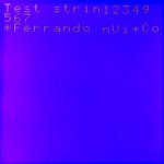
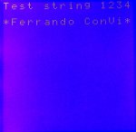
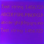
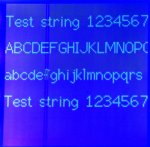
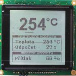
I'm trying to print some characters on my LCD using an 8051, it all seems to be ok, but i have a question, why does the screen looks like flashing and printing some garbage characters on the screen?

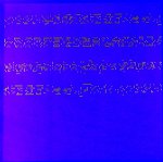
I've tryied to clear the RAM so the garbage could be deleted by writing a space character, but when i get the cursor address back to 0x0000 and write something up, at the end of the string it prints garbage data again.

I don't know if there is some way to change the refresh cycles of the screen, i've tryied to set the display duty to lower than 64 and the screen stopped flashing but i got the string printed on every row of the screen.

I hope someone could help me with this. Thank you.

By the way i'm a mexican sorry for my bad english.
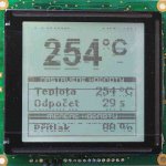
Looking for additional LCD resources? Check out our LCD blog for the latest developments in LCD technology.
 
What happens if you set the duty to 128 (Nx register content = 127)? You could post your initialization settings. A photo would be helpful.
 

ferco

New member
I've already tryied that, and the string doesn't repeat as with a 64 duty cycle, but the flashing of the screen (not the backlight) goes slower.

This is my initialization:
Code:
Instruction Reg.              Data
00H                               34H
01H                               FFH
02H                               67H
03H                               3FH
04H                               00H
08H                               00H
09H                               00H
0AH                               00H
0BH                               00H
 
Some of your init values are peculiar.

Mode (00H, 34H) is for character mode, cursor on. That seems OK.

Character pitch (01H, FFH) is a abnormal value. That would be a row-to-row spacing (Vp) of 16 pixels, and Hp must be less than 8. A more normal setting would be F7H. This may not really matter, as bit 3 is forced to 0, but I'm not sure.

Character number (02H, 67H) is saying you have 104 characters per row. If your characters are 8 pixels wide (Hp = 7), then Hn should be 15 (0FH) = 16 characters per row.

After changing the above register value, I would still try the duty factor Nx = 128 (03H,7FH).

Try these changes and see what happens.
 

ferco

New member
Hey thanks cosmicvoid!!

I think that the flashing screen was because of the 104 characters on a row, because it has been solved. Your recomendations worked very well, but...

I has a problem like the one "jeff" has with his graphic mode and the swap columns, I'm trying to display the following string " Fernando ConVi ", that'a a 16 character string, and I've intialized the number of characters to 16 = 0FH and this is what i got:

#characters
0Fh " Fernando nVi Co " cursor at next line (like should be)
10h " Fernando _ ConV" (the "_" is the cursor)
11h " Fernando _ ConV"
12h " Fernando ConVi " cursor not seen
13h " Fernando ConVi " cursor not seen
14h " Fernando ConVi " cursor not seen
15h " Fernando ConVi " cursor not seen

So i don't know what's going on.

Now, I tryied a larger string "I am testing the character mode of the CFAG128128 LCD"

And this is printed:
I am testi theng
characterode m
of the CFA2812G1
8 LCD_

And i noticed that in the first row " the", on the 2nd row "ode", 3th row "2812" are printed at a lower position, one line beneath the 8th pixel line.
 
Ok, good so far. I don't know what to make of the column swapping, before your and 'jeff' posts, I have not heard of it. I think this is the key to the problem:
in the first row " the", on the 2nd row "ode", 3th row "2812" are printed at a lower position, one line beneath the 8th pixel line.
but I can't figure out what is wrong.

Unfortunately, I currently do not have either a 128128 nor a 160160 display to experiment with, so I can not try to reproduce the symptom. Oh, BTW, I notice that the # of characters (Hn) is supposed to be an even value. Have you tried a setting less than 16 (e.g. 0Dh = 14) to see if the long string wraps at the 14th character?

I would experiment with the duty cycle (Nx) numbers a bit more, too. Also, try character pitch 01h, 77h or 97h. Sorry I can't suggest anything else at this time.
 

ferco

New member
Well, i've tryied all your recomendations, but non of them worked. I'm working now on graphic mode and i have exactly the same problem as "jeff". A column swaping. :confused:

So i did what worked for me on the character mode, setting a 20 bytes on each rows, and filling the 17th, 18th, 19th and 20th byte with 00h and the graphic was ok, it displays the image just as it should be, BUT...

I think the RAM has the capacity to store 16Mb (128x128) so... by doing what i did about the 20 bytes per row, i can draw just like 102 rows (2MB/20 = 102.4), and i'm suposing this because the bottom of the image doesn't appear on screen.

I'm running out of ideas, i've tryied playing with the display duty, and can't do it work :(

I hope someone could help me with this.
 
I will be receiving a display module from CF this coming week, so maybe I will be able to reproduce the problem, and troubleshoot it.
 

ferco

New member
I think it wasn´t the ram of the LCD, i´ve just usted an external eeprom to store 2 images, to display on 2 CFAG128128 doing what i told, about adding 4 extra bytes on every row, and by doing this the column swapping is solved, and i´ve got the images just as it should be printed.

Anyway, that´s not a good thing for memory because insted of using 2MB for a 128x128 bits image i´m needing 2.5 MB, i´m wasting memory. I´ll just keep working on it to get the image using just 2MB, like should be, if you (cosmicvoid) get the answer please let me know.
 
I have received a display to use for testing/troubleshooting, graciously provided by CF Tech support, and I have some answers for the problems seen with the CFAG128128. My setup uses a Zilog Z8 Encore development board, and the code is written in C, but that doesn't affect the results.

In text mode, I used "Test string 1234567", and "*Fernando ConVi*" (using '*' instead of spaces). The 1st photo is showing the text with the columns swapped (Hn=15), as you experienced, the 2nd photo is normal display (Hn=19).

In graphics, the 3rd photo shows 4 bitmap text strings, with the display init as Hn=15, Nx=127, and screen size defined as 128 x 128 in the code (i.e. what you think would be the correct settings). The 4th photo shows Nx=159, Hn=15, and screen size defined as 160 x 160 in the code; the columns are swapped as you and 'Jeff' experienced. The 5th photo shows the correct display, with Nx=159, Hn=19, and screen size 160 x 160.

So my conclusion is that even though this is a 128 x 128 display screen, it will only operate correctly when treated like a 160 x 160 display, and you're only using the upper-left 128 x 128 part of the array. Your code must init the display as if it was 160 pixels wide and 20 bytes/characters per row, and a duty cycle of 160; and then in your code you must keep from writing off the visible area.

In some of the photos, especially #5, you can see two vertical lines about 1/4 of the way from the left side, which makes it look like there are 'dropouts' in the characters. These are apparently defective columns, and I haven't been able to do anything to fix those, so just ignore it.

If you need more info, let me know.
 

Attachments

Last edited:

ferco

New member
Hey, thanks a lot cosmicvoid!

I've been doing great doing what i told you, which matches with your conclusion, only that i'm using an Nx=128 and it has been working just fine.

The only issue now it's about the memory i'll need to store 500 images, 4Bytes per row it's a lot when working with that amount of images. Anyway, it seems that there is no other solution, so i'll have to do that.

Thanks again.

Greetings from Mexico. :)
 

snoopy-km

New member
Hi, I have a similar problem with my lcd. Lcd is Winstar WG128128B-TFK with controller LC7981 (and uC is ATmega64). I sended bytes to right positions of the lcd memmory, but sometimes (at some addresses) bytes appears at the wrong positions of the display.

First idea - set lcd registers according to Sanyo datasheet (for 128x128) pic1.jpg:

glcd_putdata(SET_LCD_MODE, 0x32); // graphic mode
glcd_putdata(SET_CH_PITCH, 0x07); // 8 bits per byte
glcd_putdata(SET_CHAR_NUM, 16-1); // bytes per line
glcd_putdata(SET_TIME_DIVS,0x7F); // duty cycle 0x7F = 128-1
glcd_putdata(SET_CURS_POS, 0x07);
glcd_putdata(SET_HOM_L_ADDR, 0);
glcd_putdata(SET_HOM_H_ADDR, 0);
glcd_putdata(SET_CUR_L_ADDR, 0);
glcd_putdata(SET_CUR_H_ADDR, 0);

Second idea - cosmicvoid tips for lcd 128x128 with LC7981 - set reg. as 160x160 display (such as lcd duty and char. number) pic2.jpg:

glcd_putdata(SET_LCD_MODE, 0x32); // graphic mode
glcd_putdata(SET_CH_PITCH, 0x07); // 8 bits per byte
glcd_putdata(SET_CHAR_NUM, 20-1); // bytes per line
glcd_putdata(SET_TIME_DIVS,0x9F); // duty cycle 0x9F = 160-1
glcd_putdata(SET_CURS_POS, 0x07);
glcd_putdata(SET_HOM_L_ADDR, 0);
glcd_putdata(SET_HOM_H_ADDR, 0);
glcd_putdata(SET_CUR_L_ADDR, 0);
glcd_putdata(SET_CUR_H_ADDR, 0);

look at the pics... pls
any idea?
Thanks
 

Attachments

Assuming its not due to noise or other problems in your wiring, you should attach your code file for examination. I wonder if your I/O timing is marginal.
 

snoopy-km

New member
Thanks for reply. OK, here is my code (Atmega64, 16MHz):

Code:
#define LCD_DATA_PORT   PORTC
#define LCD_DATA_DDR    DDRC
#define LCD_DATA_PINS   0xFF
#define DB0             PC7
#define DB1             PC6
#define DB2             PC5
#define DB3             PC4
#define DB4             PC3
#define DB5             PC2
#define DB6             PC1
#define DB7             PC0

#define LCD_CMD_PORT    PORTD
#define LCD_CMD_DDR     DDRD
#define LCD_CMD_PINS    0xF8
#define RS              PD7
#define RW              PD6
#define E               PD5
#define CS              PD4
#define RES             PD3

#define SET_LCD_MODE    0x00
#define SET_CH_PITCH    0x01
#define SET_CHAR_NUM    0x02
#define SET_TIME_DIVS   0x03
#define SET_CURS_POS    0x04
#define SET_HOM_L_ADDR  0x08
#define SET_HOM_H_ADDR  0x09
#define SET_CUR_L_ADDR  0x0A
#define SET_CUR_H_ADDR  0x0B
#define LCD_WR_DATA     0x0C
#define LCD_RD_DATA     0x0D
#define LCD_CLEAR_BIT   0x0E
#define LCD_SET_BIT     0x0F

GLOBAL void glcd_init()  {              
  LCD_DATA_DDR = LCD_DATA_PINS;         // setup DDR register as outputs...
  LCD_DATA_PORT = 0x00;                 // ...with log.0 at outputs       
  LCD_CMD_DDR = LCD_CMD_PINS;           // setup DDR register as outputs...
  LCD_CMD_PORT = 0x00;                  // ...with log.0 at outputs   

  delay_ms(10);
  CLEARBIT(LCD_CMD_PORT, RES);		// reset glcd
  delay_ms(1);   
  SETBIT(LCD_CMD_PORT, RES);
  delay_ms(10);    
  }

GLOBAL void glcd_graphic_init()  {  
  glcd_putdata(SET_LCD_MODE, 0x32);     // graphic mode
  glcd_putdata(SET_CH_PITCH, 0x07);     // 8 bits per byte
  glcd_putdata(SET_CHAR_NUM, 20-1);     // bytes per line 
  glcd_putdata(SET_TIME_DIVS,0x9F);     // 0x9F = 160-1; 0x7F = 128-1 
  glcd_putdata(SET_CURS_POS, 0x00);     
  glcd_putdata(SET_HOM_L_ADDR, 0x00);
  glcd_putdata(SET_HOM_H_ADDR, 0x00);
  glcd_putdata(SET_CUR_L_ADDR, 0); 
  glcd_putdata(SET_CUR_H_ADDR, 0);  
  }

GLOBAL void glcd_putdata(UINT8 cmd, UINT8 data)  {  
  CLEARBIT(LCD_CMD_PORT, CS);             // #CS = 0  -> chip select  
  SETBIT(LCD_CMD_PORT, RS);               // RS = 1   -> byte to instruction register
  CLEARBIT(LCD_CMD_PORT, RW);             // R/#W = 0 -> set write to lcd
  send_8bit(cmd);  
  CLEARBIT(LCD_CMD_PORT, RS);             // RS = 0   -> byte to data register  
  CLEARBIT(LCD_CMD_PORT, RW);             // R/#W = 0 -> set write to lcd
  send_8bit(data);  
  SETBIT(LCD_CMD_PORT, CS);               // #CS = 1  -> chip de-select
  }

LOCAL void send_8bit(UINT8 temp)  {
  LCD_DATA_PORT = 0x00;  
  if((temp & 0x80) >> 7) SETBIT(LCD_DATA_PORT, DB7);
  if((temp & 0x40) >> 6) SETBIT(LCD_DATA_PORT, DB6);
  if((temp & 0x20) >> 5) SETBIT(LCD_DATA_PORT, DB5);
  if((temp & 0x10) >> 4) SETBIT(LCD_DATA_PORT, DB4);
  if((temp & 0x08) >> 3) SETBIT(LCD_DATA_PORT, DB3);  
  if((temp & 0x04) >> 2) SETBIT(LCD_DATA_PORT, DB2);
  if((temp & 0x02) >> 1) SETBIT(LCD_DATA_PORT, DB1);
  if((temp & 0x01) >> 0) SETBIT(LCD_DATA_PORT, DB0);
 
  SETBIT(LCD_CMD_PORT, E);              // E = 1  
  delay_us(1);    
  CLEARBIT(LCD_CMD_PORT, E);            // E = 0     
  delay_us(100);    
  }
 
Well, your code looks OK, at least superficially. Since you didn't *attach* (not post within text body) your whole file, including the image data writes, I can't try to run your code on my setup. The first thing I would try is playing with the SET_CHAR_NUM value, since it looks like you have a "wrap-around" situation. Maybe:

glcd_putdata(SET_CHAR_NUM, 16-1);

Note: my experiments in using the 128128 init'd as a 160160 were in character mode, not graphic mode, so I don't know how the display will react.

Also, I can't help but wonder why you do this:
Code:
  LCD_DATA_PORT = 0x00;  
  if((temp & 0x80) >> 7) SETBIT(LCD_DATA_PORT, DB7);
  if((temp & 0x40) >> 6) SETBIT(LCD_DATA_PORT, DB6);
  if((temp & 0x20) >> 5) SETBIT(LCD_DATA_PORT, DB5);
  if((temp & 0x10) >> 4) SETBIT(LCD_DATA_PORT, DB4);
  if((temp & 0x08) >> 3) SETBIT(LCD_DATA_PORT, DB3);  
  if((temp & 0x04) >> 2) SETBIT(LCD_DATA_PORT, DB2);
  if((temp & 0x02) >> 1) SETBIT(LCD_DATA_PORT, DB1);
  if((temp & 0x01) >> 0) SETBIT(LCD_DATA_PORT, DB0);
instead of this:
Code:
  LCD_DATA_PORT = temp;
Edit: oh, I see now, you've swapped the bit order on your port. Well, then you could actually get rid of the bit shifts (">> 7", etc), as they will make no difference in the bit test; it just is a waste of cpu time. Or maybe your compiler is clever enough to optimize by removing the shifts.

I don't have any other suggestion at this time.
 
Last edited:

snoopy-km

New member
Thanks for your time,
I know, this part of my code is redundant (in this case). I tested lcd on my own development kit with ATmega64, next application will have some differences between pin designations (easy to use another LCD_DATA_PORTxy). And yes, you're right I get out bit shift ...and about compiler intelligence: I don't think so :eek:)

Finally, I fixed the problem. Still it isn't a 100% corrected, but it displays what I want.

Code:
#define CONST 16	// bytes per line -> glcd_putdata(SET_CHAR_NUM, CONST-1);

GLOBAL void glcd_pos(UINT8 vertical, UINT8 horizontal)  { 
  UINT16 temp;

// ----------------------------------------------------------------------------
//  Address correction
// ----------------------------------------------------------------------------
  if ((vertical ==  8 || vertical == 16 || vertical == 24 || vertical == 32 || 
       vertical == 40 || vertical == 48 || vertical == 56 || vertical == 64 || 
       vertical == 72 || vertical == 80 || vertical == 88 || vertical == 96 ||    
       vertical ==104 || vertical ==112 || vertical ==120)) {
    temp = ((vertical-8) * CONST) + horizontal;
// ----------------------------------------------------------------------------
      }
  else  {
    temp = (vertical * CONST) + horizontal;          
    }
  glcd_putdata(SET_CUR_H_ADDR, temp >> 8);       // cursor high address setting
  glcd_putdata(SET_CUR_L_ADDR, temp & 0x00FF);   // cursor low address setting
  }

Summary, WG128128B-TFK with LC7981 in graphic mode (duty cycle is always for 128 rows, captions is in czech lang.):
1) pic1: CONST = 16, it's a correct value from Sanyo datasheet for 128x128px display
2) pic2: CONST = 20, image is correctly "glued-on", but some of addresses points to wrong space (20 ~ 160x128px)
3) pic3: CONST = 32, simillar problem as 2), but you can see a same shift at some positions (32 ~ 256x128px)
4) pic4: CONST = 32 with "Address correction"
 

Attachments

CF Tech

Administrator
A suggestion for the C code

I think this would work:
Code:
GLOBAL void glcd_pos(UINT8 vertical, UINT8 horizontal)
  { 
  UINT16
    temp;
  //Correct the address
  if (vertical &0x07)
    //not a multiple of 8, no correction
    temp = (vertical * CONST) + horizontal;          
  else
    //is a multiple of 8, do the correction
    temp = ((vertical-8) * CONST) + horizontal;

  glcd_putdata(SET_CUR_H_ADDR, temp >> 8);       // cursor high address setting
  glcd_putdata(SET_CUR_L_ADDR, temp & 0x00FF);   // cursor low address setting
  }
A bit cleaner:
Code:
GLOBAL void glcd_pos(UINT8 vertical, UINT8 horizontal)
  { 
  UINT16
    LCD_Address;

  //Correct the address
  if (!(vertical &0x07))
    //is a multiple of 8, do the correction
    vertical-=8;

  LCD_Address = (vertical * CONST) + horizontal;          

  glcd_putdata(SET_CUR_H_ADDR, LCD_Address >> 8);       // cursor high address setting
  glcd_putdata(SET_CUR_L_ADDR, LCD_Address & 0x00FF);   // cursor low address setting
  }
 
Top