CFAF320240F-T-TS Interface Help

maxwell

New member
Hi, I'm working on a capstone project at my university and am trying to implement a touchscreen for user input. I am using the CFAF320240F-T-TS touchscreen and am trying to write to the screen using a PIC16F877A. I have started trying to write my own driver for the screen so that I can write images (All I really want is a fairly simple UI). I've been reading through the datasheet for both the onboard controller (SSD2119) and the screen itself (the .pdf included by CrystalFontz). Additionally, I've read the sample code that is attached for the screen (I think it's written for an AVR).

Basically, I'm not really sure where to start. haha I'm not really sure what the commands in the sample code are doing to talk to the controller (i.e. write_command and write_data). I also keep seeing the pin CD in the code and don't see any pins labeled CD on the pinout of the screen... I was pretty much just going to duplicate the code that is used for the AVR so that I can implement it on my PIC. Does anyone know of some pre-made code that can be used as a driver that is written for PIC's? I would rather not write my own driver, but if I have to, what am I supposed to do for the CD pin?

I was also wondering if the backlight should light up when hooked up to a voltage source or does everything have to be set up through the controller? I applied 3.3V to the all of the power supply pins of the screen and nothing happened at all. I understand you have to go through a sequence of events to turn the screen on, but I thought the backlights would come on at least...

Any help is appreciated! Also, sorry if this isn't extremely coherent, I'm on some allergy medication right now and am pretty drowsy...

-Max
Looking for additional LCD resources? Check out our LCD blog for the latest developments in LCD technology.
 
I have no experience with this display, but I can answer a couple of your questions.

The CD signal is used to select between Command and Data when writing to the controller. This signal is also known as Register Select (RS) and is on pin 13. Interestingly, on page 5 of the CFA data sheet, it is referred to as "D/C not", while on page 6 it is referred to as "RS".

The backlight is powered separately from the logic, as far as I can tell, using pins 47-50 on the connector. You'll need to use current limiting resistor(s) on the LED strings (shown in the diagram on page 7). The spec is 9.9vf @ 12.5 mA per string, so you will probably want to use a 12 volt supply for that, with a 160 or 180 ohm resistor in series with each leg.

I can't help you with software at this point, sorry. I understand the process of initializing displays by writing setup values to various registers, but I'm not familiar with the details of how this controller operates.

If you have a big budget ($700+), you can get a driver library from Ramtex.
http://www.ramtex.dk/gclcd/glcd0129.htm?gclid=CLG_pOHLm6ACFQaiagodFns87A
 

maxwell

New member
Thanks for the response. I was able to get the backlight working with your help. Now, I'm having issues getting my driver to work on my PIC. I'm using a driver that was posted on this forum a while back and can't figure out why it isn't working. Here's the code:

Code:
#include <16F877A.h>
#fuses XT,NOWDT,NOPROTECT,LVP
#use delay(clock=4000000)


#define	LCD_CD	PIN_A1
#define	LCD_WR  PIN_A2
#define	LCD_RD  PIN_A3
#define	LCD_CS	PIN_A0
#define	LCD_RES	PIN_A4

#define CLR_CD OUTPUT_LOW(LCD_CD)
#define SET_CD OUTPUT_HIGH(LCD_CD)

#define CLR_CS OUTPUT_LOW(LCD_CS)
#define SET_CS OUTPUT_HIGH(LCD_CS)

#define CLR_RESET OUTPUT_LOW(LCD_RES)
#define SET_RESET OUTPUT_HIGH(LCD_RES)

#define CLR_WR OUTPUT_LOW(LCD_WR)
#define SET_WR OUTPUT_HIGH(LCD_WR)

#define CLR_RD OUTPUT_LOW(LCD_RD)
#define SET_RD OUTPUT_HIGH(LCD_RD)

// color definitions
#define	BLACK	  0x0000
#define	BLUE	  0x001F
#define	RED 	  0xF800
#define	GREEN   0x07E0
#define CYAN	  0x07FF
#define MAGENTA 0xF81F
#define YELLOW  0xFFE0
#define WHITE	  0xFFFF

/*************************************************/
void write_command(int16 command)
{
	CLR_CS;
	CLR_CD;
	SET_RD;
	SET_WR;

	output_b(command>>8);
	CLR_WR;
	SET_WR;
	delay_us(1);
	output_b(command);

	CLR_WR;
	delay_us(1);
	SET_WR;
	SET_CS;
}

/*************************************************/
void write_data(int16  data)
{
	CLR_CS;
	SET_CD;
	SET_RD;
	SET_WR;

	output_b(data>>8);
	CLR_WR;
	SET_WR;
	delay_us(1);
	output_b(data);

	CLR_WR;
	delay_us(1);
	SET_WR;
	SET_CS;
}
/*************************************************/
void initialization()
{
	SET_RD;
	SET_WR;
	SET_CS;
	SET_CD;
	output_b(0x00);

	CLR_RESET;
	delay_ms(1000);
	SET_RESET;
	delay_ms(50);

	write_command(0x0001);    // Driver Output Control Register (R01h)
	write_data(0x0000);       // Page 14, SPFD5408B Datasheet

	write_command(0x0002);    // LCD Driving Waveform Control (R02h)
	write_data(0x0700);       // Page 15, SPFD5408B Datasheet

	write_command(0x0003);    // Entry Mode (R03h)
	write_data(0x50A0);       // Page 15, SPFD5408B Datasheet

	write_command(0x0004);    // Scaling Control register (R04h)
	write_data(0x0000);       // Page 16, SPFD5408B Datasheet

	write_command(0x0008);    // Display Control 2 (R08h)
	write_data(0x0207);       // Page 17, SPFD5408B Datasheet

	write_command(0x0009);    // Display Control 3 (R09h)
	write_data(0x0000);       // Page 18, SPFD5408B Datasheet

	write_command(0x000A);    // Frame Cycle Control (R0Ah)
	write_data(0x0000);       // Page 19, SPFD5408B Datasheet

	write_command(0x000C);    // External Display Interface Control 1 (R0Ch)
	write_data(0x0000);       // Page 20, SPFD5408B Datasheet

	write_command(0x000D);    // Frame Maker Position (R0Dh)
	write_data(0x0000);       // Page 21, SPFD5408B Datasheet

	write_command(0x000F);    // External Display Interface Control 2 (R0Fh)
	write_data(0x0000);       // Page 21, SPFD5408B Datasheet

	write_command(0x0010);    // Power Control 1 (R10h)
	write_data(0x0000);       // Page 22, SPFD5408B Datasheet

	write_command(0x0011);    // Power Control 2 (R11h)
	write_data(0x0007);       // Page 23, SPFD5408B Datasheet

	write_command(0x0012);    // Power Control 3 (R12h)
	write_data(0x0000);       // Page 24, SPFD5408B Datasheet

	write_command(0x0013);    // Power Control 4 (R13h)
	write_data(0x0000);       // Page 25, SPFD5408B Datasheet
	delay_ms(200);

	write_command(0x0007);    // Display Control (R07h)
	write_data(0x0101);       // Page 16, SPFD5408B Datasheet

	write_command(0x0010);    // Power Control 1 (R10h)
	write_data(0x12B0);       // Page 22, SPFD5408B Datasheet

	write_command(0x0011);    // Power Control 2 (R11h)
	write_data(0x0007);       // Page 23, SPFD5408B Datasheet

	write_command(0x0012);    // Power Control 3 (R12h)
	write_data(0x01BB);       // Page 24, SPFD5408B Datasheet
	delay_ms(50);

	write_command(0x0013);    // Power Control 4 (R13h)
	write_data(0x1300);       // Page 25, SPFD5408B Datasheet

	write_command(0x0029);    // NVM read data 2 (R29h)
	write_data(0x0010);       // Page 30, SPFD5408B Datasheet
	delay_ms(50);

	write_command(0x0030);    // Gamma Control 1
	write_data(0x000A);       // Page 32, SPFD5408B Datasheet
	write_command(0x0031);    // Gamma Control 2
	write_data(0x1326);       // Page 32, SPFD5408B Datasheet
	write_command(0x0032);    // Gamma Control 3
	write_data(0x0A29);       // Page 32, SPFD5408B Datasheet
	write_command(0x0033);    // Gamma Control 4
	write_data(0x290A);       // Page 32, SPFD5408B Datasheet
	write_command(0x0034);    // Gamma Control 5
	write_data(0x2613);       // Page 32, SPFD5408B Datasheet
	write_command(0x0035);    // Gamma Control 6
	write_data(0x0A0A);       // Page 32, SPFD5408B Datasheet
	write_command(0x0036);    // Gamma Control 7
	write_data(0x1E03);       // Page 32, SPFD5408B Datasheet
	write_command(0x0037);    // Gamma Control 8
	write_data(0x031E);       // Page 32, SPFD5408B Datasheet
	write_command(0x0038);    // Gamma Control 9
	write_data(0x0706);       // Page 32, SPFD5408B Datasheet
	write_command(0x0039);    // Gamma Control 10
	write_data(0x0303);       // Page 32, SPFD5408B Datasheet
	write_command(0x003A);    // Gamma Control 11
	write_data(0x0E04);       // Page 32, SPFD5408B Datasheet
	write_command(0x003B);    // Gamma Control 12
	write_data(0x0E01);       // Page 32, SPFD5408B Datasheet
	write_command(0x003C);    // Gamma Control 13
	write_data(0x010E);       // Page 32, SPFD5408B Datasheet
	write_command(0x003D);    // Gamma Control 14
	write_data(0x040E);       // Page 32, SPFD5408B Datasheet
	write_command(0x003E);    // Gamma Control 15
	write_data(0x0303);       // Page 32, SPFD5408B Datasheet
	write_command(0x003F);    // Gamma Control 16
	write_data(0x0607);       // Page 32, SPFD5408B Datasheet

	write_command(0x0050);    // Window Horizontal RAM Address Start (R50h)
	write_data(0x0000);       // Page 32, SPFD5408B Datasheet
	write_command(0x0051);    // Window Horizontal RAM Address End (R51h)
	write_data(0x00EF);       // Page 32, SPFD5408B Datasheet
	write_command(0x0052);    // Window Vertical RAM Address Start (R52h)
	write_data(0x0000);       // Page 33, SPFD5408B Datasheet
	write_command(0x0053);    // Window Vertical RAM Address End (R53h)
	write_data(0x013F);       // Page 33, SPFD5408B Datasheet

	write_command(0x0060);    // Driver Output Control (R60h)
	write_data(0x2700);       // Page 33, SPFD5408B Datasheet
	write_command(0x0061);    // Driver Output Control (R61h)
	write_data(0x0001);       // Page 35, SPFD5408B Datasheet

	write_command(0x006A);    // Vertical Scroll Control (R6Ah)
	write_data(0x0000);       // Page 35, SPFD5408B Datasheet

	write_command(0x0080);    // Display Position - Partial Display 1 (R80h)
	write_data(0x0000);       // Page 35, SPFD5408B Datasheet
	write_command(0x0081);    // RAM Address Start - Partial Display 1 (R81h)
	write_data(0x0000);       // Page 35, SPFD5408B Datasheet
	write_command(0x0082);    // RAM Address End - Partial Display 1 (R82h)
	write_data(0x0000);       // Page 36, SPFD5408B Datasheet
	write_command(0x0083);    // Display Position - Partial Display 2 (R83h)
	write_data(0x0000);       // Page 36, SPFD5408B Datasheet
	write_command(0x0084);    // RAM Address Start - Partial Display 2 (R84h)
	write_data(0x0000);       // Page 36, SPFD5408B Datasheet
	write_command(0x0085);    // RAM Address End - Partial Display 2 (R85h)
	write_data(0x0000);       // Page 36, SPFD5408B Datasheet

	write_command(0x0090);    // Panel Interface Control 1 (R90h)
	write_data(0x0010);       // Page 36, SPFD5408B Datasheet
	write_command(0x0092);    // Panel Interface Control 2 (R92h)
	write_data(0x0000);       // Page 37, SPFD5408B Datasheet
	write_command(0x0093);    // Panel Interface control 3 (R93h)
	write_data(0x0103);       // Page 38, SPFD5408B Datasheet
	write_command(0x0095);    // Panel Interface control 4 (R95h)
	write_data(0x0210);       // Page 38, SPFD5408B Datasheet
	write_command(0x0097);    // Panel Interface Control 5 (R97h)
	write_data(0x0000);       // Page 40, SPFD5408B Datasheet
	write_command(0x0098);    // Panel Interface Control 6 (R98h)
	write_data(0x0000);       // Page 41, SPFD5408B Datasheet

	write_command(0x0007);    // Display Control (R07h)
	write_data(0x0173);       // Page 16, SPFD5408B Datasheet
}


/*************************************************/
void Display_Home()
{
	write_command( 0x0020); // GRAM Address Set (Horizontal Address) (R20h)
	write_data( 0x0000);
	write_command( 0x0021); // GRAM Address Set (Vertical Address) (R21h)
	write_data( 0x0000);
	write_command(0x0022);  // Write Data to GRAM (R22h)
}
/*************************************************/
void display_rgb(int16 data)
{
	int16 i,j;
	Display_Home();

	for(i=0;i<320;i++)
	{
		for(j=0;j<240;j++)
		{
			write_data(data);
		}
	}
}
/*************************************************/

void LCD_test()
{
	int16 i,j;
	Display_Home();

	write_data(BLACK);
	delay_ms(1000);
	write_data(BLUE);
	delay_ms(1000);
	write_data(GREEN);
	delay_ms(1000);
	write_data(CYAN);
	delay_ms(1000);
	write_data(RED);
	delay_ms(1000);
	write_data(MAGENTA);
	delay_ms(1000);
	write_data(YELLOW);
	delay_ms(1000);
	write_data(WHITE);

}

/*************************************************/
void main()
{
	output_low(PIN_C2);
	output_b(0xF8);	    // pull-up on switches, all others off

	output_a(0xFE);	    // all pins high

	// Initialize the display
	initialization();

	LCD_test();

blinkLED:	output_low(PIN_C2); //Blinks LED upon completion
	delay_ms(1000);
	output_high(PIN_C2);
	delay_ms(1000);
	goto blinkLED;
}
/*************************************************/
Anyone have any thoughts on why this isn't putting out anything to the pins?
 
Anyone have any thoughts on why this isn't putting out anything to the pins?
I presume you have set your ports to outputs.
Code:
TRISA = 0;
TRISB = 0;
TRISC = 0;
//etc
I don't see any evidence of this in your code, though.

What are you using to tell that nothing is being output?
 

maxwell

New member
I was thinking about trying that out, also. I haven't included that in my code as of right now, but have heard that this isn't absolutely necessary and if you try to output something on a pin, it sets the tristates to output for you and vice versa.

I also noticed that it looks like the LCD_test() function just writes 8 or so different pixels and does nothing else. I'm wondering if instead of write data, those are supposed to be the display_rgb() functions so that the screen is one solid color.

I'm using an oscilloscope to look at the various pins of A and B and they all seem to be doing nothing at all. I've checked the oscillator to make sure it is putting in 4 MHz like it should be and it seemed good. I also checked to make sure the voltages to the PIC are correct, and those seem to be good. Not really sure what else could be going on.

-Max
 
... have heard that this isn't absolutely necessary and if you try to output something on a pin, it sets the tristates to output for you and vice versa.
That is the first I've heard of it, and I tend to disbelieve it. I haven't use any PIC chips in quite a while, though. But robust programming means not leaving anything assumed; I'd put those TRIS statements in.
I'm wondering if instead of write data, those are supposed to be the display_rgb() functions so that the screen is one solid color.
You're probably right; it would make more sense.
I'm using an oscilloscope to look at the various pins of A and B and they all seem to be doing nothing at all.
Good tool to have.

Does your LED blink as expected?
Do you have a way to single step thru your code?
Have you tried to make a short loop to toggle ports A and B, to verify that they are outputting changes of state?

Some of the functions in your code aren't declared, so I can't tell if they might be problematic. If you have more than a couple dozen lines of code to post, it might be good to attach it as a file.
 

maxwell

New member
No, the LED isn't blinking either. It's almost as if the chip isn't running at all. It is really odd.

I don't have a way to single step through the code, that would be really helpful, though.

I'm going to try out the set_trisa() and set_trisb() functions tomorrow to see if they help.

I haven't made any code to toggle certain outputs as a test, but that sounds like a logical next step (though I kind of feel like this is what the blinking LED should be doing).

I can definitely attach the code as a file next time.

I can also try declaring the functions, normally if that is an issue, the compiler will freak out on me.

Thanks for all of the great suggestions.

-Max
 

maxwell

New member
So, I put the set_tris_a(0), set_tris_b(0) and set_tris_c(0) statements at the top of my main. This didn't change anything.

I also tried some basic code that should send a square wave with a period of 200 ms out of C3 and that apparently didn't work. The code is as follows:
Code:
main(){
	set_tris_a(0);
	set_tris_b(0);
	set_tris_c(0);
	while(1){
		output_low(PIN_C3);
		delay_ms(100);
		output_high(PIN_C3);
		delay_ms(100);
	}
}
The weirdest thing is that I programmed the controller with other code that I know works on another board and everything worked as it should! The only real difference that I can think of between the two boards is that I am running the board I am working with currently at 3.3V because the screen can't have more than 3.6V going into it (for the logic) while the other board is run at 5V. Any ideas?

-Max
 
Is the PIC soldered to a dev board, or is it socketed and you are moving it from one board to another?

Use the scope to see if the crystal is oscillating.
Make sure the reset pin isn't being held active.

Be aware that some port pins are shared for other functions in the cpu. Make sure that the alternate functions are disabled. For example, on reset, port A is set as analog inputs. Other ports are just set as inputs at reset.

Try toggling all 3 ports, full byte instead of single bit.

If you don't see any action on any pin, your cpu may be dead. Can't think of any other suggestions just now.
 

maxwell

New member
Okay, thanks for the help cosmic void. The datasheet for my PIC said that it could be run on between 2 and 5 volts, but when lowering the voltage down from 5V it stopped working at 4V. This was my problem and I am now working on creating buffers to lower the output voltage from 5V to 3.3V so I can still run the chip at 5V. Though I'll probably be needing further assistance in the near future :)

-Max
 

Rsocor01

New member
Maxwell,

Did you make this display work? What PIC are you using? I am using a PIC18F4550. Are you using C language or PicBasic Pro. Do you mind posting your code?

Robert
 

maxwell

New member
No, I haven't been able to get the screen to work. As I said in my last post, I needed to put level shifters to step the output voltage from my PIC down from 5V to 3.3V. Now, my PIC is running, but it is tough to tell whether the output is correct. I am using a driver that was posted on the forum earlier and tailored it a little bit for myself by putting the correct header file (I'm using a PIC16F877A) and setting the fuses that I wanted to use. The person that posted it earlier said they were able to get output, but all that I'm getting is a white screen... Not really sure what's going on. I've attached the driver that I am using, but again, it isn't working for me so I'm not sure if it will help.

-Max
 

Attachments

Rsocor01

New member
Maxwell,

I know C language but I am using PicBasic Pro for my program. It is easier for me. I will post my program when I get home.

I am also getting a white screen only. I was using 8-bit 8080 interface but no luck with that. I wrote some code for a 4-wire SPI interface and I will try that next. Let's see if I have a better luck with that.

About your power issues, you should be able to run your 16F877A at 3.3V. Try a blinking LED first. I am running my PIC at 3.3V.

Robert
 

maxwell

New member
I'm currently trying the parallel 8-bit 8080 interface, also.

I thought that I could run my PIC at that voltage also, but I did some simple code like you were talking about (a square wave out of one of the pins) and as I lowered the voltage it stopped working at 4V.

You said in one of your earlier posts that you found drivers on Microchip's website. Where did you find those? I tried a search on their website for TFT LCD driver and couldn't find anything useful.
 
I thought that I could run my PIC at that voltage also, but I did some simple code like you were talking about (a square wave out of one of the pins) and as I lowered the voltage it stopped working at 4V.
It probably stops working because you are using XT oscillator mode. Try using HS mode, and I bet it will work below 4 volts.
 

maxwell

New member
So, after using my oscilloscope to analyze the output of the pins, I've noticed that pins A1, A3, and A4 are constant. A1 is my data or command pin and is constantly high (that can't be good), A3 is my read strobe signal and it is constantly high, and A4 is my reset pin and it is constantly low (might be okay). I have code running that is supposed to flash a green screen and then a blue screen and repeatedly do this. The screen is white. I have attached the code that I currently have running. Here is all that is in my main:

Code:
void main()
{
	set_tris_a(0);
	set_tris_b(0);
	set_tris_c(0);

	output_b(0xF8);	    // pull-up on switches, all others off

	output_a(0xFE);	    // all pins high

	// Initialize the display
	initialization();

	while(1){
		display_rgb(GREEN);
		delay_ms(1000);
		display_rgb(BLUE);
		delay_ms(1000);
	}
}
Any ideas?
 

Attachments

Rsocor01

New member
You said in one of your earlier posts that you found drivers on Microchip's website. Where did you find those? I tried a search on their website for TFT LCD driver and couldn't find anything useful.
Microchip has a library for graphics LCDs. Try the following links.

http://www.microchip.com/stellent/idcplg?IdcService=SS_GET_PAGE&nodeId=2608&page=1&param=en532061

http://www.microchip.com/stellent/idcplg?IdcService=SS_GET_PAGE&nodeId=2680&dDocName=en543091

Good point made by cosmicvoid about the oscillator settings. Your PIC should definitely work with 3.3V.

Robert
 

maxwell

New member
I changed that fuse to HS and it still wouldn't work below 4V. This really isn't my issue anymore, though, as I have put level shifters on the outputs of the PIC to fix this problem. I just have a white screen. Is there any simple way to figure out if my screen is just blown?

-Max
 
I've noticed that pins A1, A3, and A4 are constant. A1 is my data or command pin and is constantly high (that can't be good), A3 is my read strobe signal and it is constantly high, and A4 is my reset pin and it is constantly low (might be okay).
A constant low on reset will hold the display in reset state.
Is there any simple way to figure out if my screen is just blown?
You need to disconnect your level shifters and display, and find out why port A outputs are not behaving as expected, before you can suspect the display of being dead.
 

Rsocor01

New member
I feel your pain Maxwell.

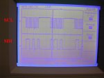
I just tried to make this display work with a 4-wire SPI interface and all I could see was a white screen :(. I connected SCL (clocking) and SDI (data in) to my oscilloscope and I could see all the clock pulses and the data bits been sent to the LCD. I checked that all my PIC pins were sending data to the LCD but still all I got was a white screen.

Before I tried with 8-bit 8080 and no luck either. I suspect the initialization of the LCD is the issue or the LCD is bad. I just don't know.

Robert
 

Attachments

Top