CFAF320240F-T-TS HEEEEELP!!! White Screen Only

Rsocor01

New member
Hi all,

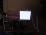
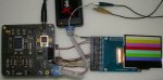
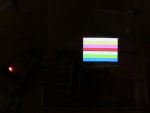
We bought this display to include it in one of our products. After many days of banging my head against the walls trying to make it work, all I can get is a white screen. First, I started with 8-bit 8080 configuration with no luck. So now, I'm trying a 4-wire SPI interface, but still no luck at all. The wiring was done according to a table recommended by CF_Tech in one of his recent posts. I am using a PIC18F4550 at 48MHz.

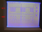
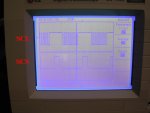
I used an oscilloscope to check that all my PIC ports are working properly. Attached is part of the program that I'm using. It is writen in PicBasic Pro, but if you know C it should be very easy to follow.

At this point I am completely clueless, so any help will be greatly appreciated.

Sincerely,

Robert
Looking for additional LCD resources? Check out our LCD blog for the latest developments in LCD technology.
 

Attachments

Right now I'm ignoring your SPI bit banger, assuming it works right (your scope traces looked reasonable). Looking at your initialization sequence, I see that some register writes are made to the same register multiple times ($00, $07). Whats with that? Comparing to the CFA sample file, you have a lot fewer registers being set (6), and CFA sets 29 registers. I guess the gamma tables aren't important, and I haven't actually bothered to look at what each register value does.

But the upshot is this: why don't you take the CFA init values from the sample file and try those?

For your screen fill, you are writing pixels of R G B R G B R G B etc,etc. Seems to me that would look approximately white. Maybe you should try for a solid fill with one color at a time.
 

CF Tech

Administrator
In general talking to a display in parallel mode will be easier than SPI mode.

If there is some trouble getting the parallel mode to work, that should be solved first before trying SPI.

Granted, either should work.

I agree with cosmicvoid, you should write some pattern of data. Just a number increasing by one each step would verify a pattern of some kind on the screen.

With all the wires to keep track of, it is very possible that there is a wiring error. The only way I know to check that is to write test loops for each bit of data going from the processor to the display. Run the test loop and make sure the corresponding pin on the display connector toggles. This is slow going, but the only sure fire way to make sure your software is really doing what you think at the display.

There can also be trouble with the power supply, poor grounding, and perhaps ringing that may be causing trouble. Does the PIC have a slew rate-limited port setting? That may help. Or try putting a 50 ohm resistor in series with the clock line (to reduce high-frequency transients) combined with slowing the clocks down to the kilohertz region.

(ascend soapbox)
The days are coming to an end when the breadboard and wires approach to prototyping are still useful. Have you considered using a service like Accutrace? They will build 10 PCBs for you in about 2 weeks, for $110 shipped.

This is not a beginner display, and unless your processor is pretty beefy you may not be happy with the performance even if it is working. One of the reasons that the demo board is delayed is that the TFTs bring even a 16MHz ATMega to its knees :(
(descend soapbox)

We can build up a demonstration for you. Unfortunately, we do not have a ready-made demo board for sale yet, but we could create a hand-made demo starting with the CFA-10006 (AVR) platform and wiring it to the display through an adapter board. This is how we took the photograph on the site.
 

Rsocor01

New member
Thank you all for your comments,

I included all the 29 register settings as recommended by both of you but still no change. I made red=255, green=0, and blue=0. Also, a 50 Ohms was added inseries to the clocking line.

HTML:
LOOKUP J,[$28,$00,$10,$01,$02,$03,$11,$0F,$0B,$0C,$0D,$0E,$1E,$25,$26,$4E,$4F,$12,_
$30,$31,$32,$33,$34,$35,$36,$37,$3A,$3B,$07],DATA_STATUS    
        
LOOKUP J,[$00,$00,$00,$32,$06,$6A,$68,$00,$53,$00,$00,$2E,$00,$80,$78,$00,$00,$08,_
$00,$01,$01,$03,$05,$03,$07,$03,$12,$08,$00],DATA_STATUS    
            
LOOKUP J,[$06,$01,$00,$EF,$00,$38,$70,$00,$08,$03,$0A,$00,$BE,$00,$00,$00,$00,$D9,_
$00,$04,$00,$05,$05,$05,$07,$00,$00,$00,$33],DATA_STATUS
With all the wires to keep track of, it is very possible that there is a wiring error. The only way I know to check that is to write test loops for each bit of data going from the processor to the display. Run the test loop and make sure the corresponding pin on the display connector toggles. This is slow going, but the only sure fire way to make sure your software is really doing what you think at the display.
I have checked the wiring many times with the help of a regular meter to check for continuity and everything seems to be ok.

This is not a beginner display, and unless your processor is pretty beefy you may not be happy with the performance even if it is working. One of the reasons that the demo board is delayed is that the TFTs bring even a 16MHz ATMega to its knees
Well, this makes me feel better. I have years of experience programing PICs, but with graphics LCDs I'm a rookie. It looks like I chose a tough cookie for my first GLCD experience. Still, I think I have digested very well the datasheet, but there is something that I must be missing. The PIC18F4550 is a very powerfull microprocessor. It is used for USB applications.

About the power issues, I am ussing a battery bank to obtain 12V and convert it to 3.3V with the help of a regulator. A 50 Ohms resistor in series with the clockink signal is already in place. I will try to get my 12V from a power transformer. Maybe the grounding is better with the transformer.

We can build up a demonstration for you. Unfortunately, we do not have a ready-made demo board for sale yet, but we could create a hand-made demo starting with the CFA-10006 (AVR) platform and wiring it to the display through an adapter board. This is how we took the photograph on the site.
That would be good. But, I think with a very simple and well explained example writen in C, I can make it work. What kind of demonstration would that be? I want to stay with the PICs. I don't know anything about the ATMega controllers.

Thank you for your help.

Robert
 

Rsocor01

New member
Hi all,

Well, I don't know if this display is fried. I should have said that the very first few times that I was playing with this display I used two voltage regulators to get the power from 12V. A 5V regulator was connected to the PIC and a 3.3V regulator was connected to the LCD. After I tested it a few times, I realized that I was doing something not too smart because 5V were comming out of the logic PIC ports into the LCD. Then, I started running the whole thing on 3.3V only, except for 12V plus a resistor for the backlighting.

Do you think that I fried the display?

I read somewhere in this forum that the LCD has some protection diodes.

Robert
 
The absolute max voltage is listed as 5v, so it doesn't seem like an obvious death sentence to the controller.

If I were in your situation, I would go back to 8 bit parallel hookup (to D10~D17), and try to see if anything can be read from the registers or GDDRAM. To do that, you would have to have a way to single-step* so you could watch the data being read, or output it to a spare port to test the value. The idea here is to see if the display can be made to respond in any fashion.

*One way to "single-step" without actual debugging hardware is to insert calls to a subroutine after every stopping place. The subroutine would turn on an LED and look at an input for a (debounced) pushbutton that signals to continue.

If that fails to produce any encouraging signs, then I'd try getting another display panel.

BTW, I see where you got the short init sequence from the SSD2119 data sheet. I wonder what difference in results you'd get, compared to the long CFA init sequence, on a known working display.

I am slightly intrigued by this display, so I ordered one to play with, but I won't get it till the end of the week.
 

Rsocor01

New member
cosmicvoid,

Thank you for your reply. I will definetely try 8-bit 8080 again to see what happens. This time I will try to slow down the speed of the PIC internal oscillator to the KHz region just for the initialization part.

It is good to know that you are getting one of these displays. It will be good to hear your feedback about this LCD.

BTW, I see where you got the short init sequence from the SSD2119 data sheet. I wonder what difference in results you'd get, compared to the long CFA init sequence, on a known working display.
Yes, I got the short init routine from the SSD2119 datasheet. In my opinion, the sample program that CF provides is part of a bigger program that does more than just testing the LCD. In the CF C program they initialize and use a SD storage card and they call many "INCLUDE" files into the main program. They do much more than just making the LCD work and that adds to the confusion of many people like me and maxwell that are trying to make this GLCD work. It would be good if CF posts a basic and simple C program that just initializes the screen and displays solid colors. This simple program would be the foundation for more complex programs created by the user. Well, I hope that the CF techs read this post and do something about it.

Robert
 
This time I will try to slow down the speed of the PIC internal oscillator to the KHz region just for the initialization part.
I'm not sure what that will prove, unless you think your timing is too fast. I'd think you'd want the same timing throughout.
... the sample program that CF provides is part of a bigger program that does more than just testing the LCD. In the CF C program they initialize and use a SD storage card and they call many "INCLUDE" files into the main program...
CFA's demo board has a SD card slot, which IMHO is an excellent way to provide large image file access to an embedded cpu. Else they would be limited to just generating boring color patterns.
It would be good if CF posts a basic and simple C program that just initializes the screen and displays solid colors.
Perhaps so. Then people would not have any examples of how to use the display in 'real' applications. It looks like you and Maxwell were able to extract a basic test program.
 

Rsocor01

New member
cosmicvoid,

Thank you for your response and for sharing your opinions.

I went back to 8-bit 8080. I'm trying to do a very simple operation, which is trying to read R00h. Please, refer to the SSD2119 datasheet v1.4 page 36. I set up a small program to do this, but I don't know if the logic of the program is correct. Needless to say that I could not see anything comming out of the LCD. All the pins at the MCU are working correctly because I checked them with an oscilloscope.

Any help will be appreciated.

Code:
Define  OSC     48                   ' Define Oscillator to 48 MHz    

TRISB = %00000000                ' SET ALL PORTS AS OUTPUTS 
TRISD = %00000000                ' SET ALL PORTS AS OUTPUTS 

HIGH PORTB.1                        'SET RD TO HIGH 
HIGH PORTB.2                        'SET WR TO HIGH   
HIGH PORTB.3                        'SET DC TO HIGH   
HIGH PORTB.5                        'SET CS TO HIGH 
PORTD = 0                            'CLEAR PORTD  

LOW PORTB.4                         'SET RESET TO LOW 
PAUSE 300
HIGH PORTB.4                        'SET RESET TO HIGH   
PAUSE 500

LOW PORTB.5                        'SET CS TO LOW
HIGH PORTB.1                        'SET RD TO HIGH 
HIGH PORTB.2                        'SET WR TO HIGH 
LOW PORTB.3                        'SET DC TO LOW
PAUSEUS 5

PORTD = 0                            'SET PORTD EQUAL TO DATA_STATUS  
PAUSEUS 1
LOW PORTB.2                        'SET WR TO LOW 
PAUSEUS 1 
HIGH PORTB.2                        'SET WR TO HIGH 
PAUSEUS 1

TRISD = %11111111               'SET ALL PORTS AS INPUTS
    
HIGH PORTB.2                        'SET WR TO HIGH   
HIGH PORTB.3                        'SET DC TO HIGH 

TESTING: 
 
LOW PORTB.5                         'SET CS TO LOW 
LOW PORTB.1                         'SET RD TO LOW

PAUSEUS 1
HIGH PORTB.1                        'SET RD TO HIGH 
PAUSEUS 1
HIGH PORTB.5                        'SET CS TO HIGH 
PAUSEUS 1

GOTO TESTING
Robert
 

Attachments

Well, I got a display delivered to me today, and spent a few hours rigging up a test setup. The first thing I tried was CFA's 8-bit C sample file, slightly modified to work on my hardware, and without the external picture slideshow.

Here is the result. So its obvious that CFA's init sequence works (as expected). I haven't tried any other experiments yet.
 

Attachments

maxwell

New member
Do you suspect that means that our screens are broken? I've tried the same initialization sequence you used and verified that the correct outputs were being put out by stepping through the sequence with a logic analyzer and for some reason I am not getting the results that you are...

Also, do you mind telling us what pins you have hooked up to what? If I'm looking at your picture right, it looks like you don't have PS3-PS0 hooked up. How did you get it to work without those? Additionally, it looks like you didn't have any problems with the ribbon being reversed at all (my pinout on the ribbon was opposite that of my breakout board). How did you get past that issue?

Thanks.

-Max
 
Last edited:
Do you suspect that means that our screens are broken? I've tried the same initialization sequence you used and verified that the correct outputs were being put out by stepping through the sequence with a logic analyzer and for some reason I am not getting the results that you are...
I have no idea whether your display is non-functional. One thing I will ask is where are you measuring the signals to verify your outputs? Unless you are measuring at the ZIF socket, then you can't be sure the display is getting those 'correct' signals.
Also, do you mind telling us what pins you have hooked up to what? If I'm looking at your picture right, it looks like you don't have PS3-PS0 hooked up. How did you get it to work without those?
For the initial test, PS0~PS3 were connected on the back of the breakout board, using wire-wrap on the tails of the header strip.
Additionally, it looks like you didn't have any problems with the ribbon being reversed at all (my pinout on the ribbon was opposite that of my breakout board). How did you get past that issue?
I used a top-contact ZIF socket, so the pin order matched the silkscreen on the breakout board. All my interconnects are made using discrete wires terminated in crimp-on receptacle pins, which are in housing strips that mate with the header strips on the cpu and breakout boards. Makes it easy to move wires, if needed.

My initial connections for the 8080 8-bit mode are:
Code:
CPU		CFAF
Port.Bit	Pin	Signal
PE.0		26	DB10
PE.1		25	DB11
PE.2		24	DB12
PE.3		23	DB13
PE.4		22	DB14
PE.5		21	DB15
PE.6		20	DB16
PE.7		19	DB17

PC.3		9	Reset
PC.4		10	CS
PC.5		13	RS
PC.6		14	WR
PC.7		7	RD
Over the weekend, I did some additional wiring to add the ability to do 16 bit transfers, and removed the mode select wire wraps, and connected PS0~PS3 to I/O port pins to allow software controlled mode.
Code:
PD.0		35	DB1
PD.1		34	DB2
PD.2		33	DB3
PD.3		32	DB4
PD.4		31	DB5
PD.5		30	DB6
PD.6		29	DB7
PD.7		28	DB8

PA.0		18	PS0
PA.1		17	PS1
PA.2		16	PS2
PA.3		15	PS3
The most interesting discovery is that using mode 8080 16 bit does not work :eek:. The screen remains blank (white). So, I will soon write some test code to output bit patterns to help me check that my new wiring is correct.
 
I must have been asleep when I did the additional wiring, as I found both ports were wired wrong. I made a little routine that puts 1 pulse on D0, 2 pulses on D1, 3 pulses on D2, etc. etc.
Code:
void port_test(unsigned char volatile far *p)
{
	uint8 bit, rep, d;
	bit = 1;
	*p = 0;
	for (rep = 1; rep <= 8; rep++)
	{
		for (d = 0; d < rep; d++)
		{
			*p |= bit;
			DLY;
			*p &= ~bit;
		}
		bit <<= 1;
		delay(10);
	}
}
which showed me the errors easily.

Now, 8080 16 bit mode works, too, and it is noticably faster than 8 bit mode.
 

Rsocor01

New member
Hi all,

Well, after many hours of loosing more hair, the good news is that I made this LCD work :) (I will post some pictures later). I was able to get a solid color displayed on the screen. Sometimes the colors that I got were not the ones that I expected but the ones that were there before. So, there goes my first question; even if you restart the power to the LCD, does the unit remember what the color that was there before is?

Now, the bad news is that it doesn't work all the times. The rest of the times I get the not so good white screen only. Sometimes I have to reset the power a few times for it to work. Usually, right after I reprogram the MCU chip it always works, but sometimes it doesn't. Also, it only works with a $300 power supply. It won't work with batteries (12V). So, I definitely have some power issues here. My next step is to solder a 1uF capacitor close to the MCU input power lines hoping that this will reduce the noise.

Are there any external components that I need to use for this LCD that I might be missing? Can you provide me with any schematics? Any tips, tricks, or advice that you could give will be greatly appreciated. Thanks.

Robert
 
Last edited:
... even if you restart the power to the LCD, does the unit remember what the color that was there before is?
If display RAM power is lost, the content will be random at next power up. Reseting and reinitializing the display does not affect the RAM content.
Are there any external components that I need to use for this LCD that I might be missing? Can you provide me with any schematics? Any tips, tricks, or advice that you could give will be greatly appreciated.
There are 3 general reasons that the display function might be inconsistant.

1. Noisy power or poor quality ground between cpu and display.

2. Noisy control or data signals.

3. Timing is too fast, i.e. setup/hold time or pulse width too short.

Signals should be measured as close to the display as practical to include the effects of the wiring. I don't recall seeing any code sample, except for your I/O test. With a 48 MHz clock, I assume you have suitable delays in your write routine.

I am surprised that you have power issues with batteries. They are typically noise free and have a low source impedance, unless you use very small batteries. Do you have input and output caps on your regulator? Regulators have been known to oscillate without them.
 

Rsocor01

New member
Hi,

Well, persistence pays off. I found the problem that I had. :) :)

I replaced the breakout board with the LCD 50-pin connector in it. I bought another breakout board and soldered a new connector to it and now it works. Now, I can start playing with this display. Thank you all that helped me, especially cosmicvoid. I'm sure I'll have more questions in the future.

Robert
 

Attachments

Top