Hi All,
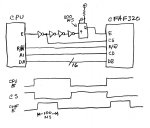
I am using this LCD with a Coldfire processor (Netburner MOD5234 module) and I have it wired for 16bit 6800 bus. I have setup the Chip Select on the processor to access this and I can see the signals on a logic analyser but I still only get a blank (white) display. I have used the code from the sample for this. Attached is the logic analyser ouput (edited to bring the signals closer together) I am sending the following config as per the sample (there is more than this, but these correspond with the logic analyser display)
write_command(0x0028); // VCOM OTP
write_data(0x0006); // Page 55-56 of SSD2119 datasheet
write_command(0x0000); // start Oscillator
write_data(0x0001); // Page 36 of SSD2119 datasheet
write_command(0x0010); // Sleep mode
write_data(0x0000); // Page 49 of SSD2119 datasheet
write_command(0x0001); // Driver Output Control
write_data(0x32EF); // Page 36-39 of SSD2119 datasheet
You can see that the correct data appears on the databus. A1 is connected to the Command/Data line so that A1 is high when I access the base address + 2. E is generated from CS2 on the processor by inverting this. CS2 is actually delayed through 4 inverting gates so that the falling edge of E is within the valid Chip Select state.
The only issue I can see is that A1 changes just at the time E falls and during the writing of the command and I am wondering if this is the reason the display is not responding. For the DATA writes, this does not appear to be the case.
The timing has wait states to meet the timing of the display and timing wise it looks ok.
Anyone spot anything I have missed or have any thoughts on getting this to work? It has to be 6800 bus as the Coldfire processor does not support the WR and RD of the 8080 bus I and I do not have any spare capacity on the GPIO lines to drive the display out of them either.
Cheers,
Dave...
Looking for additional LCD resources? Check out our LCD blog for the latest developments in LCD technology.
Attachments
-
 182.3 KB Views: 392