CFAF240400DT initialization

ukaku2

New member
sigh, i'll be honest that I am a novice to graphic lcd and mcu programming. So i suppose initial failure are in order. I have multiple projects, aside from glcd, that have been a success(i.e character lcd projects -success, ADC, servos). So anyways am just gripping incoherently here.


But in recent past, i purchased CFAF240320K-T-TS, wired it up, and it failed to run the sample code provided. then i later came to find out that i had "exploded" because i wired it up to 5 V instead of the documented 3 V. Oops.

So now i have the CFAF240400DT, connected to mcu(atmega168) @ 3 V running at 16mhz. using IM1:0 =2(decimal) for 8 bit mode(IM1:0 tied to VDD), where PORTC is control, PORTD = data.

So the issue is, when you power up the circuit, aside from the backlight lighting up, the glcd does not display a thing. Someone please tell me i made a mistake somewhere in the sample code that i modified because I am just about to pull my hair out. Note: to me it appears that the initialization code differs from the datasheet instruction, but i am assuming it is current because the sample code is tailored to this specific glcd.

So please help;
Looking for additional LCD resources? Check out our LCD blog for the latest developments in LCD technology.
 

Attachments

Assuming the init values are proper, your code looks ok, except for
Code:
	// keeps the display from going wonky -- don't know why this is.
	PORTD=0xFFFF;
	PORTD=0xFFFF;
aside from the backlight lighting up, the glcd does not display a thing.
If nothing is displayed, how can you tell that the display "goes wonky"?? I suspect you have a timing problem. Have you tried putting delays in your write functions?
Code:
void write_data(unsigned int data)
{
	CLR_CS;
	SET_CD;
	PORTD = data >> 8;	//high
	asm("nop");
	CLR_WR;
	asm("nop");
	SET_WR;

	asm("nop");
	asm("nop");
	
	PORTD = data & 0xFF;	//low
	asm("nop");
	CLR_WR;
	asm("nop");
	SET_WR;

	SET_CS;
}
IM1:0 =2(decimal) for 8 bit mode(IM1:0 tied to VDD)
This does not make sense. If IM1:0 are both tied to Vdd, then it would be IM1:0 = 3 decimal. If it really is 2 decimal, then you have 16 bit mode selected.

Here is some general advice I just gave another poster. There are 3 general reasons that the display function might be inconsistant.

1. Noisy power or poor quality ground between cpu and display.

2. Noisy control or data signals.

3. Timing is too fast, i.e. setup/hold time or pulse width too short.
 

ukaku2

New member
much regards cosmicvoid, your very helpful, although my problem is not solved yet.

So to try to remedy my problem, i took apart the circuit, wired up a new atmega324p( stock at 8mhz), tailored the demonstration code to use 16-bitmode. took care to ensure the wiring was perfect, although there is a pin referenced as ID which the datasheet directs to tied via 100k resistor to VDD. circuit is powered via 3.3 V battery, minimal noise noted with scope. I added some delay to write_data/write_command not quite sure how much delay is adequate.

-porta, low byte
-portb, high byte

-portd, control lines( please correct, but i believe CD=RS and RES = RESET)


so still, so display on the lcd. I have tried everything under the sun, i think...... please please, any further suggestions will be much appreciated.. . thank all
 

Attachments

I don't see any obvious problem in your code; I see you didn't stretch the WR pulse like I suggested. Why not? Since I don't have this display, I can't check the code for myself, and I'm too lazy to try to validate all the init settings.
... took care to ensure the wiring was perfect ...
Please tell which pins on the display your hi & lo data ports are connected to.
... circuit is powered via 3.3 V battery ...
There is some discrepancy between CFA's data sheet and the SPFD5420A data sheet regarding maximum voltage, but the recommended max Vdd seems to be 3.1 volts ...
... i believe CD=RS and RES = RESET ...
Right.

When you make scope measurements, are you testing at the tabs on the flex tail, or further back towards the cpu?
 

ukaku2

New member
1) i stretch the WR pulse:
void write_command(unsigned int command)

{
CLR_CS;
CLR_CD;
SET_RD;
SET_WR;

delay(200);

PORTA=command; //low
PORTB=command>>8; //high

CLR_WR;
SET_CS;
delay(200);
SET_WR;
}

2) PORTA = low port, PORTB = high port

3) "When you make scope measurements, are you testing at the tabs on the flex tail, or further back towards the cpu? "(cosmicvoid)
measured towards cpu
 
1) i stretch the WR pulse:
Code:
void write_command(unsigned int command) {
...snip...
	PORTA=command;				//low
	PORTB=command>>8;			//high

	CLR_WR;	[COLOR="Red"][B]// The WR pulse starts here[/B][/COLOR]
	SET_CS;	[COLOR="Red"][B]// The write action ends here[/B][/COLOR]
	delay(200); [COLOR="Red"][B]// This delay accomplishes nothing[/B][/COLOR]
	SET_WR;	[COLOR="Red"][B]// ending the WR signal here has no effect on the write[/B][/COLOR]
}
Why are you de-asserting CS while the WR pulse is active? Look at the sample I posted above:
https://forum.crystalfontz.com/showpost.php?p=28079&postcount=2
2) PORTA = low port, PORTB = high port
This is a TOTALLY useless answer. I want to know exactly which pins on the display each data port is connected to.
measured towards cpu
So, your signals look OK near the cpu, but you don't have a CLUE what they look like at the input to the display, is this right?

I'm thinking about getting a CFAF240320 or CFAF240400, I'm not sure which, to experiment with. I know you must be frustrated, and if you want to be cooperative and helpful, I am willing to spend my time trying to help you. If not, I'm outa here.
 

ukaku2

New member
okay, as far as pins on the lcd that are connected to the cpu/mcu:
DB17:10 (pin 11-18) //high
DB08:01 (pin 20-27) //low

with the scope, i checked the signal, all appear appropriate, that is with varying signals
i will follow up with the linked you provided,


again, much regards with your efforts to help; and yes, this is frustrating for me https://forum.crystalfontz.com/images/smilies/frown.gif
 

ukaku2

New member
momentary grip

I must grip for a second because i feel that i should not have this much of an issue with the code considering the fact that i used the provided "sample demonstration software, which i assumed would work with minimal modification... sigh.

anyway, one should not cry over spilled milk.

anyways, comments/input by CFAF tech support would be much appreciated. Oh, thanks all that are helping me already(comicvoid)
 
I have ordered a CFAF240400, but I probably won't get it till mid next week. Then I can make up a test jig with my CFA-10006 AVR board and try out the code.

Lets assume, for now, that the code will work. The only other things that could be wrong are:
1. display module bad (not likely in this case)
2. wiring problem (wrong pin, or bad solder joint on flex tail), poor ground between cpu and display.
3. signal/power quality (noisy, wrong voltage)

Your data connections seem to be to the proper pins; have you checked that the data bits are on the right pins? A couple weeks ago I miswired a CFAF320240. To determine the problem I wrote a small routine that puts out 1 pulse on D0, then 2 pulses on D1 , then 3 pulses on D2, etc., and called it from an infinite loop, so I could check with my scope to see the correct number of pulses on the pins of the flex tail. You might take a few minutes to try this code on each of your data and control ports, and measure at the flex tail, with scope ground at the flex tail.
https://forum.crystalfontz.com/showpost.php?p=27945&postcount=13

That will confirm both correct pin-pin wiring as well as signal quality.

Nothing else I can suggest until you give more information regarding specific symptoms you have. The symptom of "still doesn't work" is not enough to go on.
 

ukaku2

New member
wow, i greatly appreciate your efforts, especially considering that you are willing to purchase this lcd to help me out (that might be an understatement).

Clarified:
1) Power line is without noise, 3V battery(1.5+1.5),
2) mcu and lcd share common clean contact with power and ground
3) lcd is not damaged, especially considering that i tested out the code with 2 separate lcd(CFAF240400DT) without succcess.

So, i took your advice and diligently placed pulses on the data ports(PORTA/PORTB) all of which appear cleanly on the flex tail of the lcd, bit by bit(7:0). So, i assume the data is being placed on the LCD.

I suspect that the code is not being interpreted by the lcd in such a manner as to direct the lcd to carry out its function. So there in lies my frustration because the code i am using IS the demonstration code that is specific to the CFAF240400DT, of which one would assume should work with limited modification.

sigh. . . So the symptoms is that the lcd is not damaged, receives code from mcu, is powered on, but fails to display anything to the screen. The only thing that the lcd does successfully is that it powers on the back light LEDs.
 
I received a CFAF240400DT, and I've had loads of fun getting it to work :) :confused: :eek: :mad:.

I'm using your code as the base for my tests, and confirm that it isn't working. To facilitate testing, I have the mode select inputs on the display driven by port pins. As I was wiring the display to my AVR board, I noticed a discrepancy between the CFA data sheet and the SPFD5420 data sheet. The CFA sheet shows the I/F mode pins as "IM1", "IM0", and "ID". The SPFD5420 sheet show these, on pg 7, as "IM2", "IM1", and "IM0/ID". The "ID" function is an alternate use of IM0, only in serial mode, where IM0 becomes an input for the ID bit in the serial stream. So, I think the CFA data sheet is wrong, or at least very misleading, in its naming of these pins. I believe that the pins named IM1 is really IM2, IM0 is really IM1, and ID is IM0.

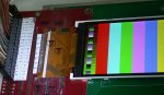
I set the mode to 010 for 16 bit, as shown on pg 7 of the SPFD5420 sheet, but that didn't help. Still no display. Then I tried mode 011 for 8 bit, and the display came to life and showed the expected color bands.

To troubleshoot the 16 bit mode problem, I made the display write functions be dynamically switchable between 16 bit (1 write) and 8 bit (2 writes), and brought in some functions from my CFAF320 code. Since 8 bit mode worked, I tried running up to the color band test in 8 bit mode, then switched to 16 bit mode to write the colors. That worked, but the colors were corrupted somewhat (in a very peculiar manner), indicating that 16 bit data writes are faulty, and thats why trying to initialize in 16 bit mode yielded no result. Next, I used my LCDRead() function to test what was being written to the display, all in 8 bit mode. For a reality check, I read the chip ID register (0), and got 0x5420. The SPFD5420 sheet, on pg 13, says 0x5408 will be read, but i think they used the 5408 data sheet as the basis for the 5420 sheet, and forgot to change the numbers in several places.

Next I wrote a series of 16 pixel patterns, a walking bit, from 0x0001, 0x0002 ... 0x4000, 0x8000. The 16 values that I read back all had 1 bit high, but the order was not the same, as though the data was shifted. I figured that it had something to do with the RGB bit order in the Entry Mode register (3). The init function writes 0x1030 to register 3, the BGR bit being high, causing the R and B colors to be swapped (to allow RGB entries, since BGR is the native sequence). I changed the init value to 0x0030, and the swapping went away, and the 16 pixel values came back exactly as written. This would only be important if you needed to do screen reads, like for screen block copies. Since the BGR sequence made the color definitions wrong, I had to redefine them with R and B swapped. Now the color bands are right again, and the reads are good.

Now, trying to write pixels in 16 bit mode, and read them back in 8 bit mode, to see whats the matter with the data. The data was corrupted, but I couldn't figure out how or why. Tried a lot of things, switching dynamically from 8 to 16 and back, to see if I could find a pattern to the corruption, but no dice. On a whim, I decided to try 18 bit (000) and 9 bit (001) modes, since the command bits are mapped the same as 8/16 bit. Surprisingly, 9 bit mode didn't work for 8 bit writes, but 18 bit mode worked for 16 bit writes. After trying these modes a bit more, I found that both 8 bit and 16 bit methods could be made to work.

modes 000 and 001 work as 16 bit transfers
modes 010 and 011 work as 8 bit transfers

This is definitely a conflict with the mode table on pg 7 of the SPFD5420 sheet. It seems that IM0 ("ID" in the CFA doc) is a "don't care", and IM1 (IM0 in the CFA doc) is the difference between 8 and 16 bit. I have no idea how 9 and 18 bit transfers are selected. Or maybe I'm using 9/18 and don't know it.

Full amplitude R G and B values look correct on the screen, but partial amplitude colors do not look right. I used a function from my CFAF320 code to write a gray scale ramp. On this display it was badly tinted with green and magenta. I thought it might be due to the gamma registers, so I commented out that part of the init sequence. That did not help. In fact, I commented out big chunks of the init function, with seemingly no ill effects. So I still haven't figured out the gray scale problem.

I am attaching my test code so you can get an idea of what I tried. It should work for you. You'll have to change the defines for port assignment and bit assignment.

BTW, I'm not seeing any problem running everything at 3.3 volts.
 

Attachments

ukaku2

New member
i have an immense amount of gratitude that i hope that you recognize, in the wake of all the effort you have exercised to help . . . but i hope i dont annoy you when i say, the code you provided, with my modification(so i can run on my chip) is displaying colors/data on the lcd.

if you could PLEASE just quickly glance over it to ensure that in the process of me modifying it that i did not rub it of its core function/usage. . . and if things check out then i can assume the lcd is faulted .

quick aside:
i wired it using 8 bit mode for simplicity, where PORTB on my chip is output for data line:
PB0=DB10
PB1=PD11
. . .
PB6=PD16
PD7=PD17

PORTC is my control line

I did make adjustments to IM1,IM0,ID to reflect the discrepancies that you noted (which by the way assures me that i am not entirely inept);

i am curious as to whether it would be possible for the lcd to be damage during soldering of the flex tail to a smd to DIPP board???(i hope that answer is NO)

so again, cosmicvoid, greatly apprepriate your help,

much much much regards
 
... but i hope i dont annoy you when i say, the code you provided, with my modification(so i can run on my chip) is displaying colors/data on the lcd.

if you could PLEASE just quickly glance over it to ensure that in the process of me modifying it that i did not rub it of its core function/usage. . . and if things check out then i can assume the lcd is faulted.
I'm puzzled by this. You say color "is displaying"... why would I be annoyed about that? Then you want me to "glance over it"... what is "it"? I see no attachment. As for assuming the display is faulted, sounds to me like you really meant "is not displaying".
quick aside:
i wired it using 8 bit mode for simplicity, where PORTB on my chip is output for data line:
PB0=DB10
PB1=PD11
. . .
PB6=PD16
PD7=PD17
Hmm, either you've got a lot of typos here or what? I presume you mean PB0:7 connects to DB10:17, which is the correct connection for 8 bit transfers.
i am curious as to whether it would be possible for the lcd to be damage during soldering of the flex tail to a smd to DIPP board???(i hope that answer is NO)
Well, sure its possible. Maybe one or more traces from the tail have broken off from the soldered tabs. But unless you are flexing the soldered tail, its not very likely. My display is soldered to a SM breakout board, and the tail is firmly taped down so that the connection can't be strained.
 

Attachments

ukaku2

New member
apologizes for the typos. i was in a hast to respond( not an excuse, am sure).

okay, yes you presumed correctly that the display does NOT display anything.

and here is the code, see attachments,
thanks
 

Attachments

Well, earlier in this thread you claim to use PORTB as the high byte and PORTA as the low byte. That is the opposite to what you've defined in the changes to the code file:
Code:
//low port out
#define OUT_LO	PORTB
#define IN_LO	PINB
#define DDR_LO	DDRB
//high port out
#define OUT_HI	PORTA
#define IN_HI	PINA
#define DDR_HI	DDRA
So I'd say its obvious that the code disagrees with your wiring. Also I see that you havent changed the control line bit assignments to match your earlier choices.

Those are good reasons for it not to work. Are you actually paying attention to detail here? :confused:
 

ukaku2

New member
certainly i am paying attention

after downloading the code from you, i did a complete overhaul of the wiring as to reflex the downloaded code.

specifically:
i do have PORTB(PB0:7) as data output wired to DB10:17.
portd as control(rd,wr,cd,cs,res,im2,im1,im0(rd=PC7 and IM0=PC0) connected to db7:0 respectively)

that is basically the core of the wiring. i purposely went with 8 bit as to reduce chances of mistake.

so i will underscore that i am, frustrating, paying due attention to by wiring and coding...so wow, i am exhaust. well, perhaps lcd programming is not my thing, but i well keep working at this.
 

ukaku2

New member
does the fact that my chip is running at 1 mhz have significance to the software not running, perhaps the varying speeds on which you tested the software conflicts with my clock speed. tAnd if so, should i had more or less delay between the write_data or write_command

hey, am just going out on a limb
 
certainly i am paying attention

portd as control (rd, wr, cd, cs, res, im2, im1, im0 (rd=PC7 and IM0=PC0)
Then why are you claiming PORTD for control, yet saying PC0~PC7?

Having a slow cpu will not make a difference except for slower performance. Mine has a 16 MHz crystal, 8 MHz clock rate I think.
 

gen4ik

New member
ich spreche leider kein englisch aber fehler lieg in CS

CS -ON
Send Command
Send DATA
CS -OFF


static void spfd5420Command(unsigned short cmmd,unsigned short data)
{
//Command
CLR_CS;//Chip select on
CLR_CD;
SET_RD;
SET_WR;
__raw_writel( cmmd, PORTD + PIO_ODSR);//PORT INIT

CLR_WR;
SET_WR;
//SET_CS;
//*********************

//Data
//CLR_CS;
SET_CD;
//SET_RD;
//SET_WR;

//dd=data & 0xFF00;
__raw_writel( data, PORTD + PIO_ODSR);//PORT INIT

CLR_WR;

SET_WR;

SET_CS;//Chip select off


//write_command(cmmd);
//write_data(data);
}
 
Top