CFAF240320K-T-TS help PLEASE!

ukaku2

New member
Hello all,

I am working with graphic lcd CFAF240320K-T-TS and trying to implement the software demonstration software provide with it using AVR Atmega324p.

Currently I have:
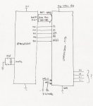
1) IM3 + IM0 tied to GND to use the 16 bit interface mode, as indicated by CFAF240320K-T-TS datasheet
2) Using PORTA as lower byte(DB7-DB0),
PORTC as higher byte(B17-D10)
PORTD as control where, PD7= CD/RS PD6 =WR PD5=RD PD4=CS PD3=0 PD2=RES PD1= 0 PD0 = 0
3) am not sure what to do with X+,Y+,X-,Y-

Problem is, the lcd does not display anything after code is compiled and download with avrdude. Please help! any help is very much appreciated
Looking for additional LCD resources? Check out our LCD blog for the latest developments in LCD technology.
 
2) Using PORTA as lower byte(DB7-DB0), PORTC as higher byte(B17-D10)
The CFA datasheet for the CFAF240320K has a suspicious difference from the SPFD5408B sheet. In the SPFD5408B datasheet, in 16 bit mode, the lower byte connects to DB1-DB8. But DB8 does not exist on the CFAF pinout, so one supposes that CFA has connected DB1-8 to DB0-7 on the flex tail. Otherwise, 16 bit mode could not work.

Just for grins :rolleyes:, maybe you could try using 8 bit mode, and write the high byte then write the low byte, both to PORTC, to see if that makes any difference.

I have just done a piece of code for the CFAF320240, which has a similar scheme, but does not use the same controller. In my code, I was able to get both 8 bit and 16 bit mode to work, but the CFAF320 has all 18 data pins on the flex tail, unlike the CFAF240.

Otherwise, without seeing your code, I cannot suggest further.
 

CF Support

Administrator
Cosmicvoid:

You are correct about the pin connections made on the flex tail, the connections are made such that DB0 and DB9 for the controller not brought out.

ukaku2:

If you can either post your code here, or send it to support@crystalfontz.com, we can take a look and see about helping you to get this going.
 

ukaku2

New member
Cfaf249320k-t-ts

Alright, please see attachments that contain my diagram and faulted code.


again,

thank you for your assistance.
 

Attachments

ukaku2

New member
I have just done a piece of code for the CFAF320240, which has a similar scheme, but does not use the same controller. In my code, I was able to get both 8 bit and 16 bit mode to work, but the CFAF320 has all 18 data pins on the flex tail, unlike the CFAF240.

Otherwise, without seeing your code, I cannot suggest further.[/QUOTE]

------------->
above i have my code listed and my diagram
 
Okey dokey, your code looks plain vanilla just like the sample, and it should work (assuming the init values are good). I don't have this display, so I can't test your code.

Let's get some assumptions out of the way...
Are you running the AVR chip and the display at 3.0 to 3.6 volts?
Are you sure that your wiring is correct?

Technically speaking, your 8-bit versions of "write_data()" and "write_command()" should work, but I suggest you not de-assert CS between bytes, and remove extra stuff:
Code:
void write_data(unsigned int data)
{
	CLR_CS;
	SET_CD;

	PORTA = data >> 8;
	CLR_WR;
	delay(1);
	SET_WR;

	delay(1);

	PORTA = data & 0xFF;
	CLR_WR;
	delay(1);
	SET_WR;

	SET_CS;
}
At one point in my code debugging, I couldn't get the 16 bit version to work, and I found I had miswired the lower byte. I used a scope and a test routine that put pulses on the port pins, 1 pulse on D0, 2 pulses on D1, 3 pulses on D2, etc. Made it easy to find my error. Do you have a scope?
You only missed the macro redefinition from portc to portd. I have fixed it and it's attached.
Yow, I must be blind:eek::(.
 

ukaku2

New member
continued issue

1) I checked my wiring from pin 1 - 37 of lcd and all check out
2) lcd is powered with ~ 3.01 V using a 3V zener diode and 46 ohm resist, but the avr chip is at 4.8 V ****is that an issue,

3) using 8 bit mode = IM3(GND) IM0(VDD)
4) download code unto chip, my test lcd works fine. Lcd backlight is on but nothing else is displaced.

at this rate i want to take a hammer to the thing, but i suppose i should practice resistant.
My code has been modified and attach. please review again.

thank you, oh, and yes i do have a scope
 

Attachments

CF Tech

Administrator
The 4.8v is troubling. Can you make your AVR operate at 3.3v? That would save a lot of trouble.

Otherwise you need a level translator.
 
I don't want to seem like an alarmist, but the spec sheet lists the absolute max input voltage as Vcc+0.3v. So you may have to consider that an input has possibly been damaged. That is a plausible explanation for why you can't get it to work.
 
Top