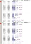
The error w/o the " " says Error [1105] symbol 'demoBG' has not been defined BUILD FAILED
Yes the images are super fast but two problems are still here...
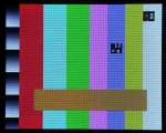
I still cannot print two different images, wrong image data.
The other is very funny... I'll illustrate it first:
take this image:
|abc.......d|
|e..........f|
|g..........h|
it prints out as:
|c......d.ab|
|.........f.e|
|.........h.g|
In words it seems to be shifted a few pixels to the right and what is cut off is put at the beginning...
Very strange.
Yes the images are super fast but two problems are still here...
I still cannot print two different images, wrong image data.
The other is very funny... I'll illustrate it first:
take this image:
|abc.......d|
|e..........f|
|g..........h|
it prints out as:
|c......d.ab|
|.........f.e|
|.........h.g|
In words it seems to be shifted a few pixels to the right and what is cut off is put at the beginning...
Very strange.
Looking for additional LCD resources? Check out our LCD blog for the latest developments in LCD technology.
")