KernelpaniK
New member
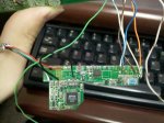
I recently decided to pull my 634 out of the parts bin and use it for a project, only issue is I couldn't find my USB cable. So I decided to solder the cables directly onto the interface board. Well long story short, a few of the solder ends came off the board and now I have no place to solder the SPI_BUSY and the DATA_IN pins that go from the interface board to the main board.
The soldering job I did is a bit messy, but it shows the boot screen of the LCD itself.
Is there a diagram somewhere that will show me at least what item on the board I need to solder those two wires into?

The soldering job I did is a bit messy, but it shows the boot screen of the LCD itself.
Is there a diagram somewhere that will show me at least what item on the board I need to solder those two wires into?

Looking for additional LCD resources? Check out our LCD blog for the latest developments in LCD technology.


